Heat exchanger and air-conditioning apparatus

Active Publication Date: 2020-06-11
MITSUBISHI ELECTRIC CORP
View PDF0 Cites 3 Cited by
  • Summary
  • Abstract
  • Description
  • Claims
  • Application Information

AI Technical Summary

Benefits of technology

[0012]According to an embodiment of the present invention, the bypass pipe is disposed between the entrance portion and the first header and configured to bypass refrigerant. The bypass pipe is provided with the flow control mechanism configured to control the flow rate of refrigerant. Consequently, gas refrigerant is directed to the bypass pipe from the second header through which refrigerant in a two-phase gas-liquid state flows. As a result, the flow of refrigerant through the header pipe of the second header can be adjusted to follo

Problems solved by technology

However, the improvement in distribution performance attained by the above-mentioned addition of structural objects to the interior of the header is small relative to the significant associated increase in cost.
The addition of structural objects is also accompanied by a significant increase in pressure loss in the header, causing a decrease in e

Method used


Image

  • Heat exchanger and air-conditioning apparatus
  • Heat exchanger and air-conditioning apparatus
  • Heat exchanger and air-conditioning apparatus

Examples


embodiment 1

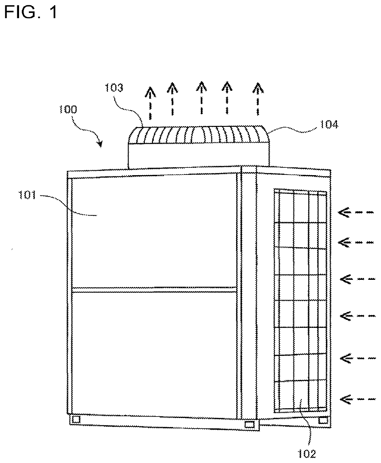
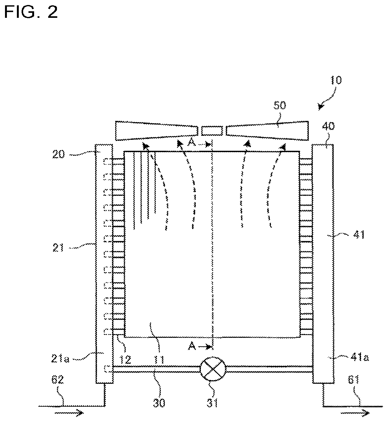
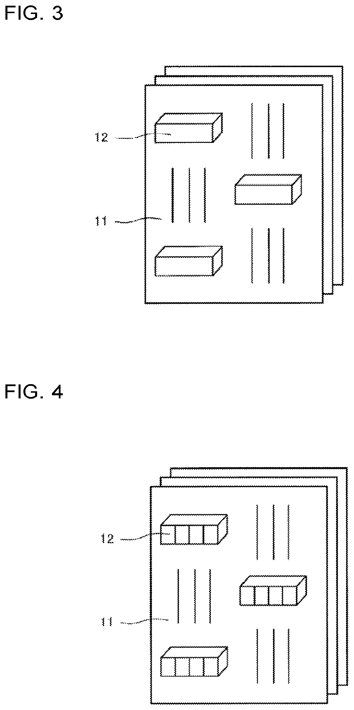
[0070]FIG. 1 is a side view of an outdoor unit 100 of an air-conditioning apparatus, according to Embodiment 1 of the present invention. FIG. 2 is a schematic side view of an outdoor heat exchanger 10, according to Embodiment 1 of the present invention. FIG. 3 is a perspective view of an exemplary cross-section of the outdoor heat exchanger 10 taken along the line A-A of FIG. 2, according to Embodiment 1 of the present invention. FIG. 4 is a perspective view of another exemplary cross-section of the outdoor heat exchanger 10 taken along the line A-A of FIG. 2, according to Embodiment 1 of the present invention. FIG. 5 is a perspective view of another exemplary cross-section of the outdoor heat exchanger 10 taken along the line A-A of FIG. 2, according to Embodiment 1 of the present invention.

[0071]The solid and broken arrows in the drawings respectively represent the flow of refrigerant and the flow of air in the outdoor unit 100 of the air-conditioning apparatus during heating oper...

embodiment 2

[0211]Embodiment 2 of the present invention will be described below. In the following, a description will not be given of features overlapping those of Embodiment 1, and portions identical or corresponding to those of Embodiment 1 will be designated by the same reference signs.

[0212]FIG. 22 is a perspective view of the second header 20, according to Embodiment 2 of the present invention. FIG. 23 is a perspective view of an example of the second header 20, according to Embodiment 2 of the present invention.

[0213]In Embodiment 2, the heat transfer tube 12 is in the form of a flat tube as illustrated in FIG. 22. Alternatively, the heat transfer tube 12 is in the form of a flat perforated tube as illustrated in FIG. 23. For the flat perforated tube configuration, partitions 12a are disposed inside the flat tube to define a plurality of holes.

[0214]As illustrated in FIGS. 22 and 23, each of the heat transfer tubes 12 is in the form of a flat tube or flat perforated tube. The heat transfe...

embodiment 3

[0225]Embodiment 3 of the present invention will be described below. In the following, a description will not be given of features overlapping those of Embodiments 1 and 2, and portions identical or corresponding to those of Embodiments 1 and 2 will be designated by the same reference signs.

[0226]FIG. 24 is a schematic side view of the outdoor heat exchanger 10, according to Embodiment 3 of the present invention. FIG. 25 is a top view of the second header 20 and the heat transfer tube 12, according to Embodiment 3 of the present invention.

[0227]In Embodiment 3, the heat transfer tube 12 is in the form of a flat tube, and the heat transfer tube 12 and the branch tube 22 of the second header 20 are connected to each other by a tube-shape transforming joint 23.

[0228]As illustrated in FIGS. 24 and 25, the heat transfer tube 12 and the branch tube 22 of the second header 20 are connected to each other by the tube-shape transforming joint 23 while having their tube shapes transformed by t...


PUM


Abstract

A heat exchanger includes a plurality of heat transfer tubes, a first header, a second header, and a plurality of fins. The heat exchanger constitutes a portion of a refrigeration cycle circuit in which refrigerant circulates. The second header includes a header pipe. The header pipe has an entrance portion. A bypass pipe is disposed between the entrance portion and the first header and configured to bypass refrigerant. The bypass pipe protrudes into the header pipe to be connected to the header pipe. The bypass pipe is provided with a flow control mechanism configured to control a flow rate of refrigerant.

Description

TECHNICAL FIELD[0001]The present invention relates to a heat exchanger and an air-conditioning apparatus that include a header through which refrigerant in a two-phase gas-liquid state flows when the heat exchanger acts as an evaporator.BACKGROUND ART[0002]In conventional air-conditioning apparatuses, liquid refrigerant condensed in a heat exchanger equipped to an indoor unit and acting as a condenser is reduced in pressure by an expansion device. The refrigerant is thus caused to change into a two-phase gas-liquid state in which the refrigerant contains both gas refrigerant and liquid refrigerant. The resulting refrigerant then flows into a heat exchanger equipped to an outdoor unit and acting as an evaporator. When refrigerant flows in a two-phase gas-liquid state into the heat exchanger acting as an evaporator, the distribution of refrigerant to the heat exchanger deteriorates. In one exemplary method for addressing this problem, to improve refrigerant distribution performance, a...

Claims


Application Information

Patent Timeline
IPC IPC(8): F28F9/02F25B41/06F28F9/04F25B39/02F25B39/04
CPCF25B2400/23F25B39/04F25B41/067F25B39/02F28F9/04F25B39/028F25B2400/0409F28F9/02F25B41/00F24F1/14F28F2210/02F28F9/0243F28F9/18F28F9/182F28F27/02F28F1/025F28F2009/0285F28D2021/0068F28F2250/06F28D1/05366
Inventor ONAKA, YOJIMATSUMOTO, TAKASHIMIYAWAKI, KOSUKEOKANO, HIROYUKIKOIKE, TAKANORIHATOMURA, TAKESHIMORIMOTO, OSAMU
Owner MITSUBISHI ELECTRIC CORP
Why Eureka
Try Eureka