Orientation insensitive refrigerant distributor tube

a technology of refrigerant distributor and orientation-sensitive, which is applied in the direction of indirect heat exchanger, lighting and heating apparatus, stationary conduit assembly, etc. it can solve the problems of poor refrigerant distribution uneven temperature distribution over the coil, and mal-distribution of refrigerant through the refrigerant tube, etc., to achieve improved heat transfer efficiency and improved refrigerant distribution

Inactive Publication Date: 2011-12-01
DELPHI TECH INC
View PDF6 Cites 31 Cited by
  • Summary
  • Abstract
  • Description
  • Claims
  • Application Information

AI Technical Summary

Benefits of technology

[0010]The above configurations of orifices on the distributor tube provide that at least one of the orifices will be located within the liquid phase of the two-phase refrigerant flowing through the distributor tube regardless of the final orientations of the evaporator coil. This provides at least the advantage of improved refrigerant distribution through the refrigerant tube of the heat exchanger assembly resulting in improved heat transfer efficiency.

Problems solved by technology

For a heat exchanger operating in evaporator mode, the increased length of the headers tends to result in refrigerant mal-distribution through the refrigerant tubes.
Momentum and gravity effects, due to the large mass differences between the liquid and gas phases, can result in separation of the phases in the inlet header and cause poor refrigerant distribution through the refrigerant tubes.
Poor refrigerant distribution degrades evaporator performance and can result in uneven temperature distribution over the coil.
Indoor evaporators also have the additional challenge of packaging constraints; the evaporators have to fit within the limited volume offered by the plenums of residential HVAC systems.
The desired distribution of refrigerant flowing through the coil may be adversely affected due to the orientation of the evaporator.

Method used


Image

  • Orientation insensitive refrigerant distributor tube
  • Orientation insensitive refrigerant distributor tube
  • Orientation insensitive refrigerant distributor tube

Examples


Embodiment Construction

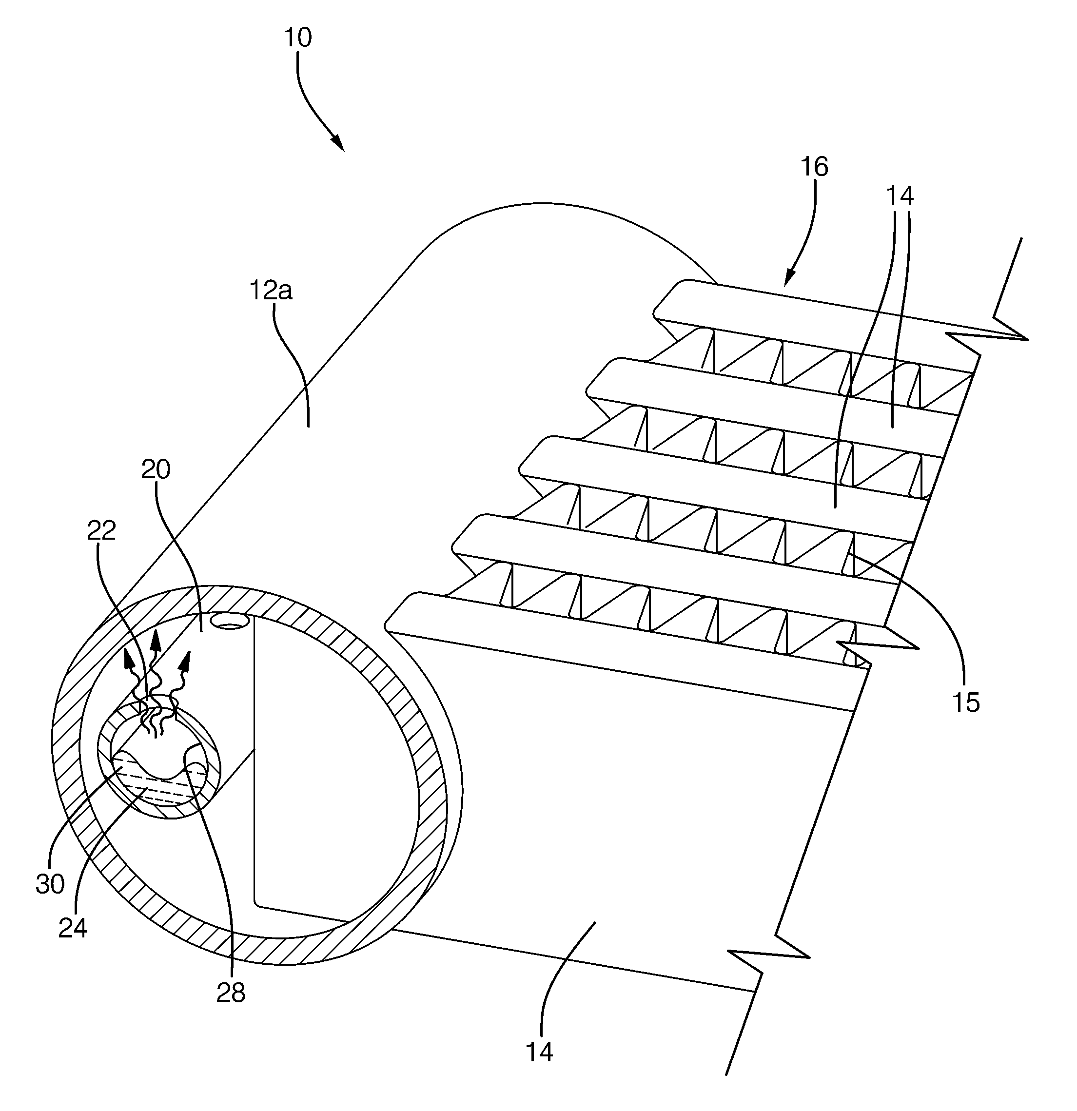
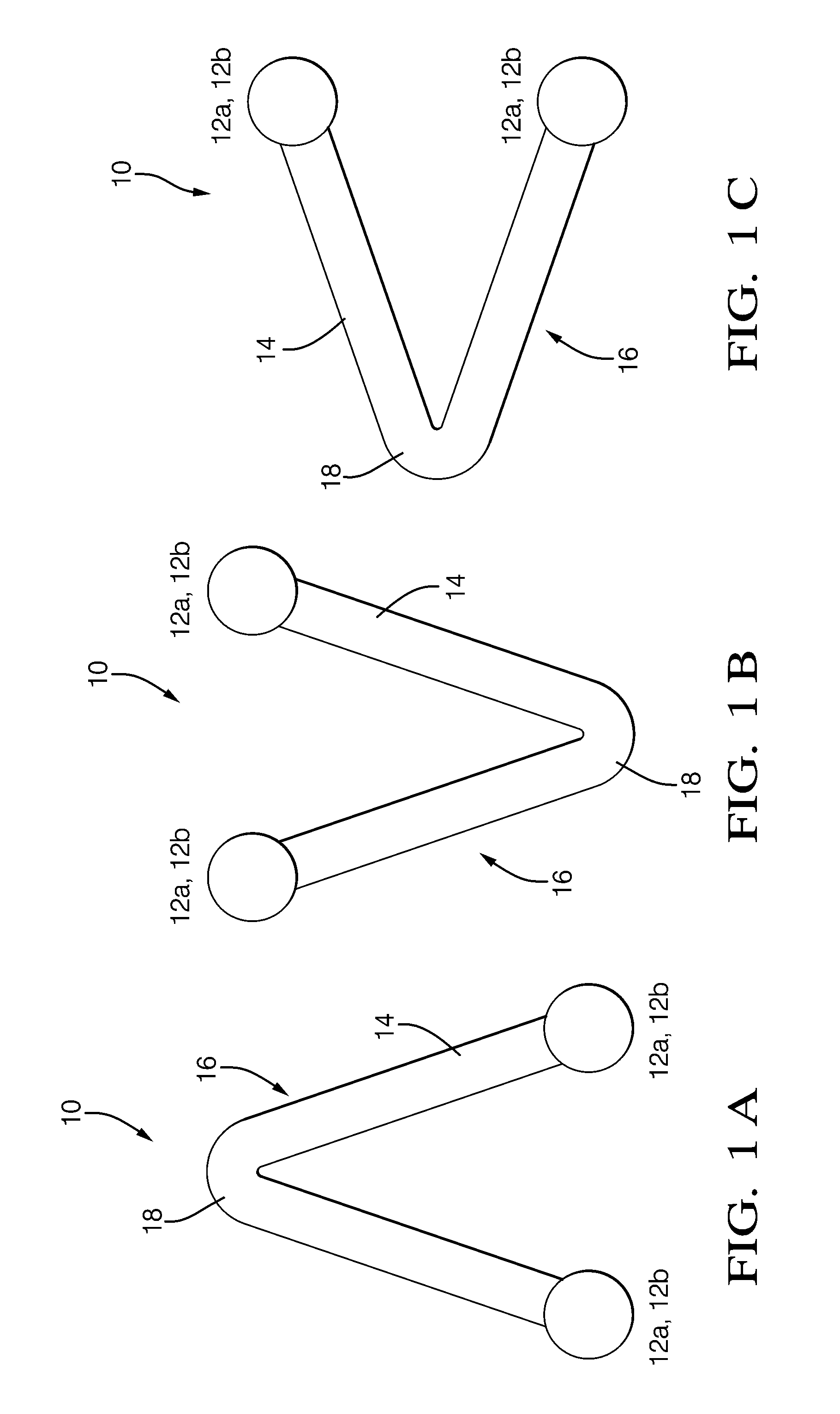
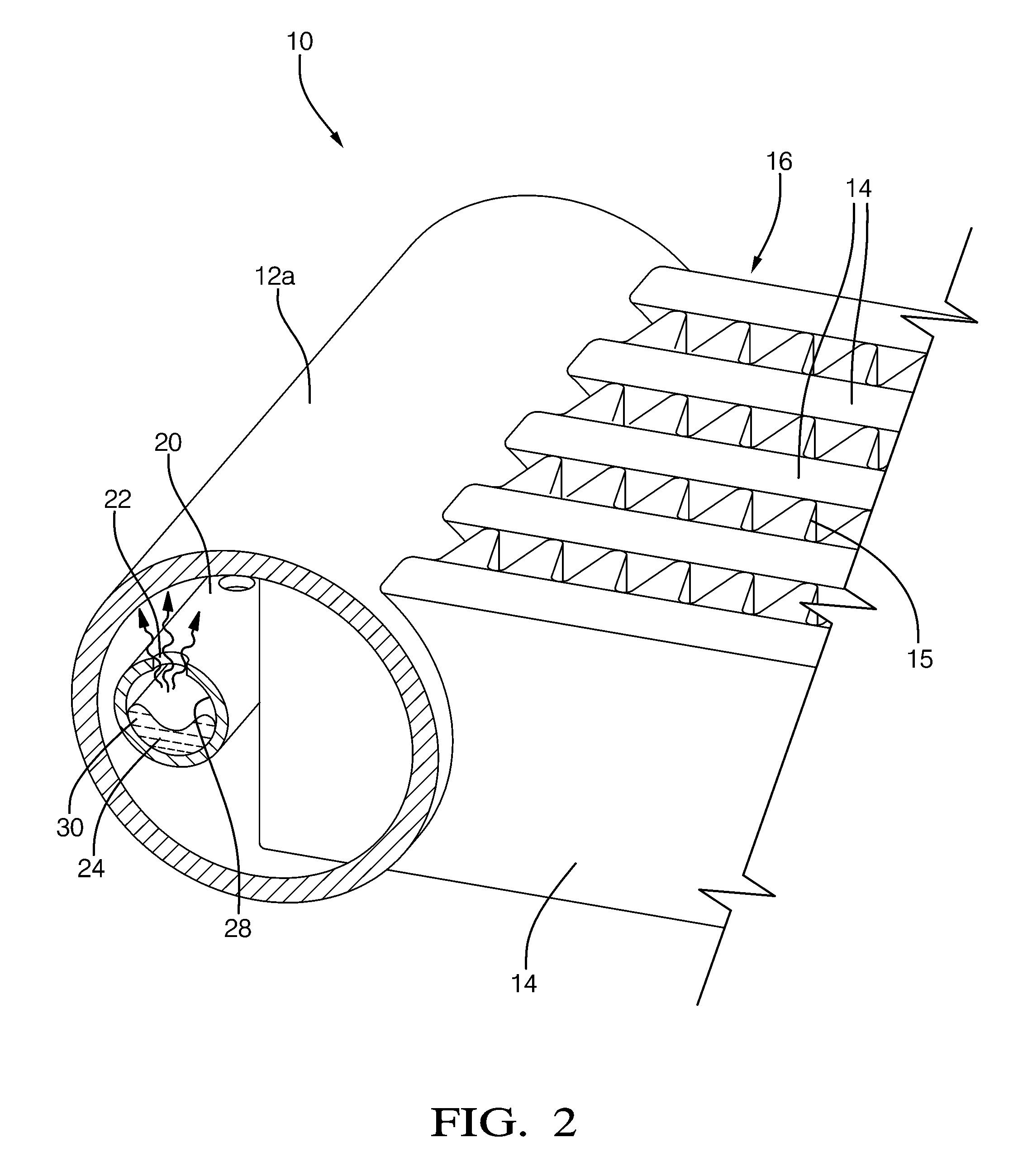
[0019]For a typical slab coil design evaporator, the desired angle of the orifices of a distributor tube is selected based on testing of a vertical slab coil in which the refrigerant tubes are aligned in the direction of gravity with the inlet header lower than the outlet header. To accommodate the packaging constraints required for residential applications, a residential indoor evaporator may be constructed by using two slab coils in an A-Frame design or a single slab coil bent into an ARC design. Shown in FIGS. 1A-1C are representations of an end view of an A-Frame design or ARC design residential indoor evaporator 10 having an inlet header 12a, an outlet header 12b spaced apart from the inlet header 12a, and a plurality of refrigerant tubes 14 hydraulically connecting the headers 12a, 12b for refrigerant flow. An evaporator coil 16, partially shown in FIGS. 2 and 3, is defined by the plurality of refrigerant tubes 14 together with external fins 15 interconnecting the adjacent ref...


PUM


Abstract

A heat exchanger assembly having an inlet header, an outlet header spaced from the inlet header, a plurality of refrigerant tubes hydraulically connecting the inlet header with the outlet header. A distributor tube having a plurality of orifices disposed in the inlet header, wherein the orifices are arranged along the distributor tube such that at least one orifice is oriented in the liquid phase of the refrigerant pressed against the internal surface of the distributor tube regardless of orientation of the evaporator. The orifices may be arranged in a random order about the distributor tube, positioned in groups of at least two at predetermined locations, or spiraled along the distributor tube.

Description

CROSS-REFERENCE TO RELATED APPLICATION[0001]This application claims the benefit of U.S. Provisional Patent Application Ser. No. 61 / 350,123 for an ORIENTATION INSENSITIVE REFRIGERANT DISTRIBUTION TUBE, filed on Jun. 1, 2010, which is hereby incorporated by reference in its entirety.TECHNICAL FIELD OF INVENTION[0002]The present disclosure relates to an inlet distributor for an evaporator; more particularly to an inlet distributor having a plurality of orifices arranged along the length of the distributor tube.BACKGROUND OF INVENTION[0003]Residential and commercial air conditioning and heat pump systems are known to employ modified automotive heat exchangers, which are desirable for its proven high heat transfer efficiency, durability, and relatively ease of manufacturability. Automotive heat exchangers typically include an inlet header, an outlet header, and a plurality of refrigerant tubes hydraulically connecting the headers for refrigerant flow therebetween. Corrugated fins interco...

Claims


Application Information

Patent Timeline
Patent Type & Authority Applications(United States)
IPC IPC(8): F28F9/02
CPCF28D1/05383F28F9/0273F28D2021/0071F28D2001/0273
Inventor JOSHI, SHRIKANT MUKUNDWINTERSTEEN, DOUGLASJOHNSON, RUSSELL SCOTTXIA, YANPING
Owner DELPHI TECH INC
Why Eureka
Try Eureka