Position controller

Active Publication Date: 2020-06-11
KAWASAKI HEAVY IND LTD
View PDF0 Cites 2 Cited by
  • Summary
  • Abstract
  • Description
  • Claims
  • Application Information

AI Technical Summary

Benefits of technology

[0026]According to the present invention, it is possible to prevent the instability of the closed-loop control after switching f

Problems solved by technology

However, at the time of startup in a cold region, response to the operation of the power roller is delayed due to a

Method used


Image

  • Position controller
  • Position controller
  • Position controller

Examples


Example

[0034]Hereinafter, embodiments will be described with reference to the drawings.

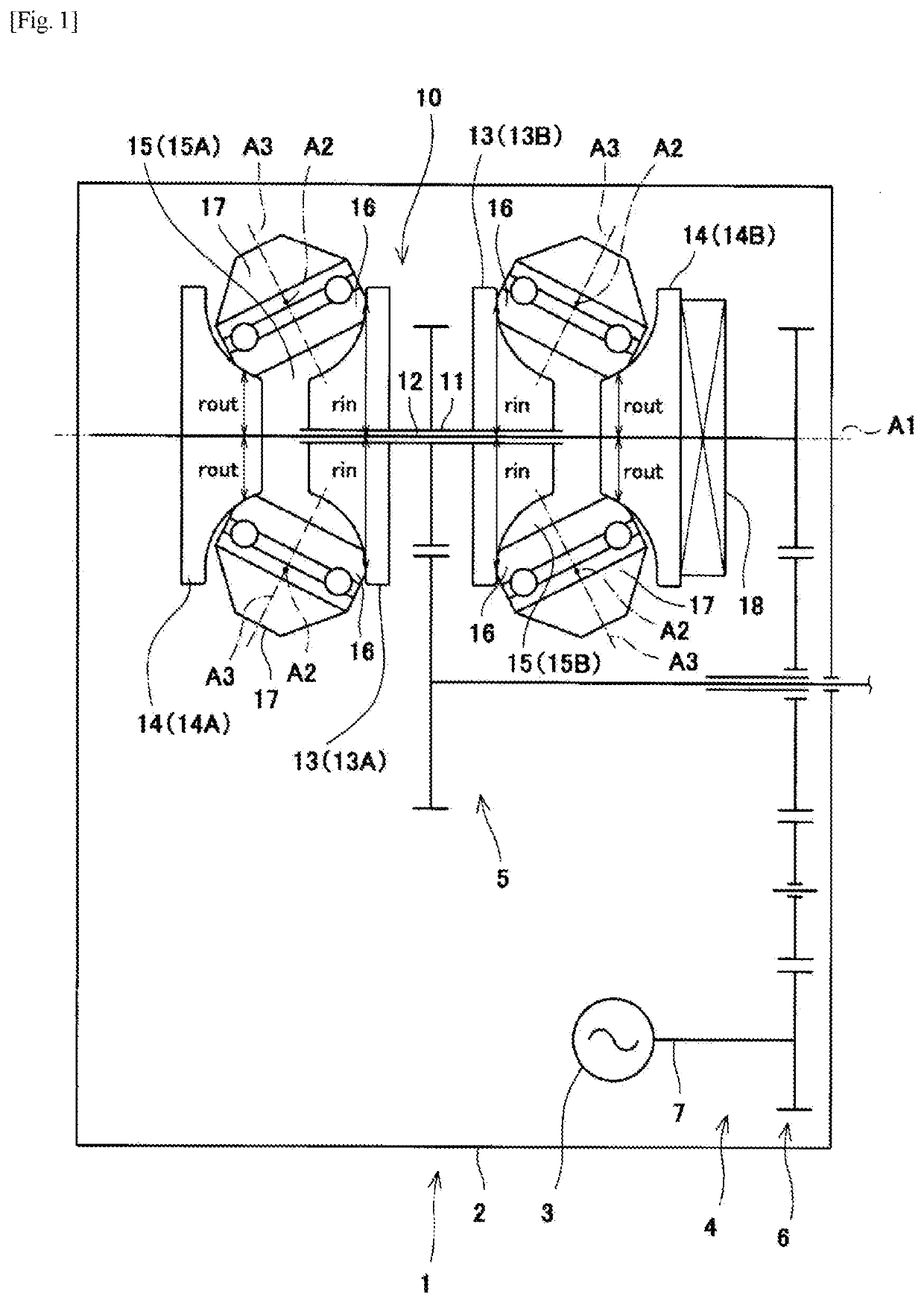
[0035]FIG. 1 is a skeleton diagram of a drive mechanism-integrated power generator 1 according to the embodiment. As shown in FIG. 1, the integrated drive generator (hereinafter referral to as “IDG”) 1 is used as an AC power supply for an aircraft. At the time of startup of the IDG1, even if rotational power of an engine rotary shaft of an aircraft starts to be transmitted to the IDG1, until the IDG1 can be stably operated, electrical components in the aircraft are driven by an auxiliary power supply that is different from the IDG1 (for example, an external generator or an auxiliary generator). When the IDG1 can be stably operated, the power supply of the electrical components is switched from the auxiliary power supply to the IDG1. Since the IDG1 is used as a main power supply of the aircraft, the power supply is switched from the auxiliary power supply to the IDG1 before takeoff.

[0036]The IDG 1 include...


PUM


Abstract

A position controller that performs position control by outputting a drive signal to a control valve of a hydraulic actuator that changes an operation position of an object, includes: a position acquisition unit that acquires an actual value of an operation position of the object; a position control unit that calculates an operation command value for the control valve by closed-loop control so as to reduce a deviation between a target value of the operation position of the object and the actual value; and a vibration wave application unit that applies a vibration wave to a signal of the closed-loop control so that the operation command value vibrates at a predetermined frequency at start of the closed-loop control.

Description

TECHNICAL FIELD[0001]The present invention relates to a position controller that performs position control by outputting a drive signal to a control valve of a hydraulic actuator.BACKGROUND ART[0002]In a toroidal continuously variable transmission, power rollers are displaced by a hydraulic mechanism in order to change the transmission ratio. However, at the time of startup in a cold region, response to the operation of the power roller is delayed due to a decrease in fluidity of the oil, and hence a warm-up operation is required at the time of low-temperature startup. As an example of the warm-up operation, in Patent Literature 1, in the warm-up operation at the time of low-temperature startup, a spool of a control valve of the hydraulic mechanism is reciprocated within a range in which the transmission is maintained in a speed-reduced state to vibrate the piston. In this manner, low-temperature control to promote warm-up by flowing oil is performed. When the oil temperature reache...

Claims


Application Information

Patent Timeline
IPC IPC(8): G05D3/12F16H61/02
CPCF16H61/02G05D3/12F16H2061/0279F16H61/664F16H15/38F16H61/0206F16H2061/0075F16H61/00F16H2312/20B60W10/109F16H61/0265F16H59/72B60K2025/024
Inventor MATSUDA, KIPPEIKOBAYASHI, SHUMAOOTSUKI, SATOSHINAKASHIMA, KENICHIIMAI, HIDEYUKIABE, AKIHITO
Owner KAWASAKI HEAVY IND LTD
Why Eureka
Try Eureka