Vehicle stability control method and device, equipment and storage medium
A stability control and stability technology, applied in the field of equipment and storage media, devices, and vehicle stability control methods, can solve problems such as overcorrection, vehicle deviation from the existing driving road, and insufficient control, and achieve the effect of preventing instability.
- Summary
- Abstract
- Description
- Claims
- Application Information
AI Technical Summary
Problems solved by technology
Method used
Image


Examples
Embodiment 1
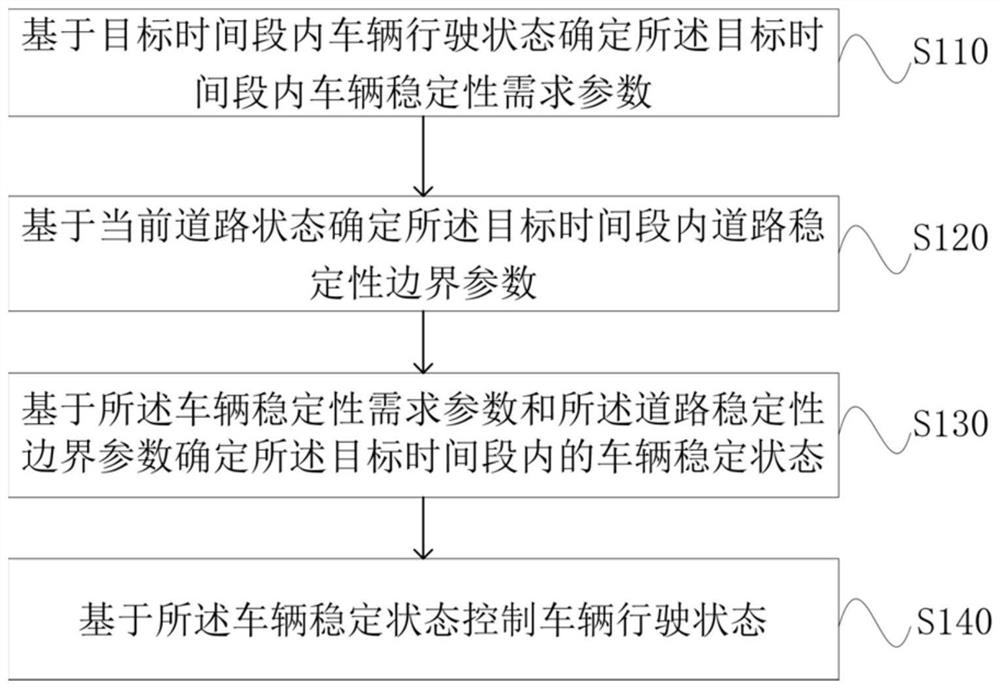
[0030] figure 1 It is a flow chart of a vehicle stability control method provided in Embodiment 1 of the present invention. This embodiment is applicable to intelligent active vehicle stability control. The method can be controlled by the vehicle stability control device in the embodiment of the present invention To execute, the device may be implemented in software and / or hardware. The vehicle stability control method provided in this embodiment specifically includes the following steps:
[0031] S110. Determine a vehicle stability requirement parameter within the target time period based on the driving state of the vehicle within the target time period.
[0032] Wherein, the target time period refers to a period of time in the future. The driving state of the vehicle includes the driving path of the vehicle and the driving speed of the vehicle. The vehicle stability requirement parameters refer to the parameters that the vehicle can meet its own needs to ensure the safe p...
Embodiment 2
[0064] figure 2 It is a flowchart of a vehicle stability control method provided in Embodiment 2 of the present invention; this embodiment is applicable to the situation of intelligent active vehicle stability control, and this embodiment further optimizes the vehicle stability control method, such as figure 2 As shown, the optimized vehicle stability control method mainly includes the following steps:
[0065] S210. Determine the vehicle driving state within the target time period based on the map information or on-board road sensor information or automatic driving planning trajectory information and the current vehicle driving state; wherein the vehicle driving state includes the vehicle driving path and the vehicle driving speed.
[0066] Specifically, the vehicle travel path and vehicle speed within the target time period can be determined through map information, on-board road sensor information, and autonomous driving planning trajectory information. The vehicle drivi...
Embodiment 3
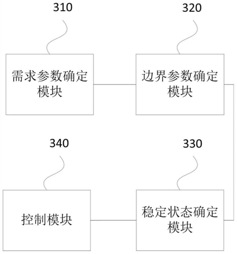
[0098] image 3 It is a schematic structural diagram of a vehicle stability control device provided in Embodiment 3 of the present invention. An embodiment of the present invention provides a vehicle stability control device, including:
[0099] A demand parameter determination module 310, configured to determine a vehicle stability demand parameter within the target time period based on the vehicle driving state within the target time period;
[0100] A boundary parameter determination module 320, configured to determine a boundary parameter of road stability within the target time period based on the current road state;
[0101] A stable state determination module 330, configured to determine the stable state of the vehicle within the target time period based on the vehicle stability demand parameter and the road stability boundary parameter;
[0102] A control module 340, configured to control the driving state of the vehicle based on the stable state of the vehicle.
[...
PUM
 Abstract
Description
Claims
Application Information