
Movable type spot welding machine capable of reducing welding slag splashing

A mobile, spot welding machine technology, applied in welding equipment, resistance welding equipment, metal processing equipment, etc., can solve the problems that affect the welding work of the spot welding machine, the electrode pressure of the spot welding machine is small, and the workpiece cannot be pressed. To achieve the effect of simple structure, saving energy and preventing breakage

Inactive Publication Date: 2018-02-09
绍兴意诺贸易有限公司
View PDF0 Cites 2 Cited by
  • Summary
  • Abstract
  • Description
  • Claims
  • Application Information

AI Technical Summary

Problems solved by technology

[0002] The mobile spot welding machine uses two electrodes to press the workpiece during welding, so that the two layers of metal of the workpiece form a contact resistance under the electrode pressure, and when the current flows from the electrode tip to the other electrode tip, an instantaneous hot-melt connection is formed on the contact resistance , to complete the welding of the workpiece; the existing mobile spot welding machine has certain disadvantages in use. The electrode pressure of the spot welding machine is too small to compress the workpiece, causing a large amount of welding slag to splash when the workpiece is processed, and the point The electrode tip of the welding machine is relatively thin, and it is easy to cause the electrode tip to break when it is stressed, which affects the welding work of the spot welder and has a certain impact on use. Therefore, we propose a mobile spot that reduces welding slag spatter. welder

Method used


Image

  • Movable type spot welding machine capable of reducing welding slag splashing
  • Movable type spot welding machine capable of reducing welding slag splashing
  • Movable type spot welding machine capable of reducing welding slag splashing

Examples


Embodiment Construction

[0017] In order to make the technical means, creative features, goals and effects achieved by the present invention easy to understand, the present invention will be further described below in conjunction with specific embodiments.

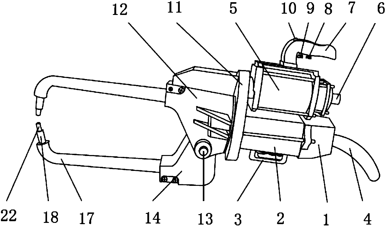
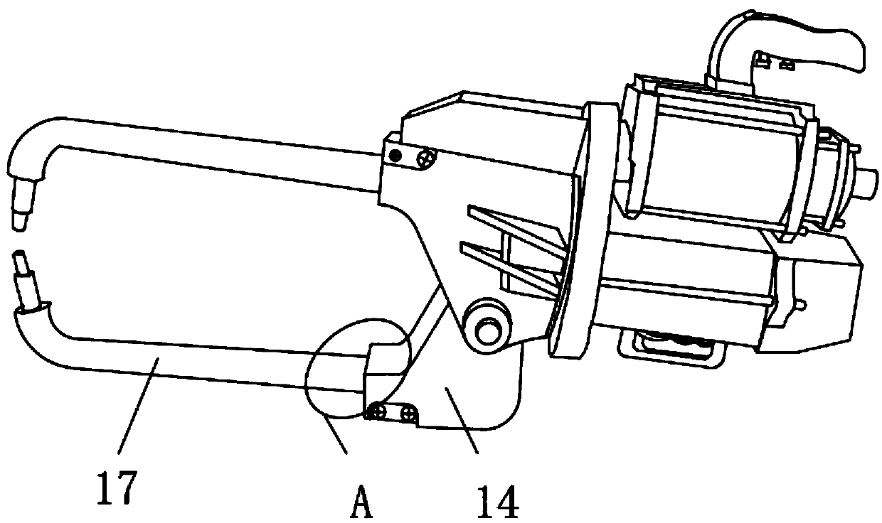
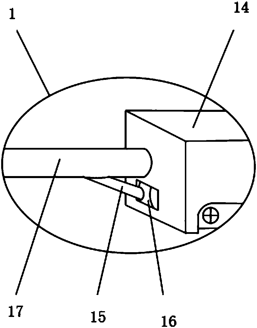
[0018] Such as Figure 1-5 As shown, a mobile spot welding machine for reducing spatter of welding slag, including a welding transformer 2, a cylinder 5 and a connection plate 11, the outer surface of one side of the welding transformer 2 is fixedly installed with a rear cover 1, and the outer surface of the lower end of the welding transformer 2 An auxiliary handle 3 is fixedly installed. When the user uses the spot welding machine, he can hold the handle 7 with one hand, and the other hand holds the spot welding machine through the auxiliary handle 3, which is convenient for the user to move the spot welding machine. Save energy, and the user can hold the spot welding machine more firmly. The outer surface of one side of the rear cover 1 is fixe...


PUM


Abstract

Disclosed is a movable type spot welding machine capable of reducing welding slag splashing. The movable type spot welding machine capable of reducing welding slag splashing comprises a welding transformer, an air cylinder and a connecting disc. A rear cover is fixedly installed on the outer surface of one side of the welding transformer, an auxiliary handle is fixedly installed on the outer surface of the lower end of the welding transformer, and a cable is fixedly installed on the outer surface of one side of the rear cover. An air valve is fixedly installed on the outer surface of one sideof the air cylinder, and a handle is fixedly installed on the outer surface of the upper end of the air cylinder. A welding button and an auxiliary stroke button are arranged on the outer surface of the lower end of the handle, and the welding button is arranged on one side of the auxiliary stroke button. According to the movable type spot welding machine capable of reducing welding slag splashing, due to the fact that the auxiliary handle, power arms and rubber gaskets are arranged, usage and movement of the spot welding machine can be facilitated, welding arms can tightly press a workpiece,welding slag splashing is reduced, the phenomenon that due to the fact that an electrode tip is excessively stressed, the damage is caused can also be avoided, and the better application prospect canbe achieved.

Description

technical field [0001] The invention relates to the field of spot welding machines, in particular to a mobile spot welding machine which reduces spatter of welding slag. Background technique [0002] The mobile spot welding machine uses two electrodes to press the workpiece during welding, so that the two layers of metal of the workpiece form a contact resistance under the electrode pressure, and when the current flows from the electrode tip to the other electrode tip, an instantaneous hot-melt connection is formed on the contact resistance , to complete the welding of the workpiece; the existing mobile spot welding machine has certain disadvantages in use. The electrode pressure of the spot welding machine is too small to compress the workpiece, causing a large amount of welding slag to splash when the workpiece is processed, and the point The electrode tip of the welding machine is relatively thin, and it is easy to cause the electrode tip to break when it is stressed, whi...

Claims


Application Information

Patent Timeline
Patent Type & Authority Applications(China)
IPC IPC(8): B23K11/11B23K11/28B23K11/36
CPCB23K11/115B23K11/28B23K11/36
Inventor 刘永远
Owner 绍兴意诺贸易有限公司
Learn More