Assisted Injection Device for Selectively Injecting a Composition Contained in a Medical Container

a technology of injection device and composition, which is applied in the direction of injection syringe, intravenous device, automatic syringe, etc., can solve the problems of repetitive strain injury, inability to stop and restart injection, and difficulty in carrying out injection of composition contained in the container with a manual injection device such as a syring

Active Publication Date: 2020-06-18
BECTON DICKINSON FRANCE
View PDF0 Cites 0 Cited by
  • Summary
  • Abstract
  • Description
  • Claims
  • Application Information

AI Technical Summary

Benefits of technology

[0015]Such an improved device allows for assisting the user for carrying out easy injection of the composition contained in the container as well as controlling the injection.

Problems solved by technology

In certain cases, the injection of the composition contained in the container with a manual injection device such as a syringe, can be difficult to carry out, due to the force that needs to be applied onto the piston rod for expelling the composition.
In the case of healthcare professionals performing repetitive injections of viscous drugs to patients, the repetition of the same gesture requiring to apply a high force onto the piston rod to perform the injection may cause repetitive strain injuries.
A consequence is that once the user has triggered the injection by pushing the button, the injection cannot be stopped and restarted again.
In particular, carrying out multiple injection sequences of fractions of the pharmaceutical composition while stopping the injection between two consecutive sequences is also not possible.
Moreover, the user cannot change the injection rate (or injection speed) while performing the injection with an autoinjector.
In other terms, it is not possible to increase or decrease the injection rate while performing the injection.
This lack of control of the injection can generate pain and anxiety to the user, and may lead the user to be unable to perform the injection correctly.
Moreover, similarly to manual injection devices, autoinjectors can encounter difficulties for injecting a composition with a high viscosity, mainly due to an insufficient force applied to the piston rod by the injection mechanism.

Method used


Image

  • Assisted Injection Device for Selectively Injecting a Composition Contained in a Medical Container
  • Assisted Injection Device for Selectively Injecting a Composition Contained in a Medical Container
  • Assisted Injection Device for Selectively Injecting a Composition Contained in a Medical Container

Examples


Embodiment Construction

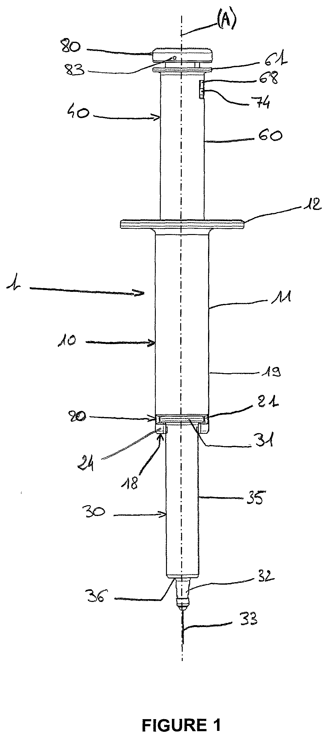
[0045]The invention proposes an assisted injection device for injecting a composition contained in a medical container.

[0046]Prior to the injection, the medical container is filled with the composition intended to be injected, and stoppered with a stopper 34 inserted therein. The stoppered medical container 30 is then mounted on the device, and the injection of the composition can be carried out.

[0047]In reference to FIG. 1, the injection device 1 comprises a main body 10 of a cylindrical shape extending along a longitudinal axis (A). The main body 10 comprises a peripheral wall 19 provided with a grip surface 11 limited proximally by a flange 12 that extends radially outwardly from the axis (A). Hence, when using the device 1, the user can easily grab the main body 10 so that the palm of his hand contacts the grip surface 11 and the upper end of his hand abuts the flange 12, thus facilitating the handling of the device. Or the user can hold the grip surface 11 between his index fin...


PUM


Abstract

The present disclosure relates to an assisted injection device for injecting a composition contained in a medical container. The injection device includes a main body adapted to receive a medical container in a fixed position relative to the main body. The main body includes an inner wall part and a second part. The first part includes an inner spring-loaded piston rod, and an outer piston body extending coaxially around the inner spring-loaded piston rod. The second part is arranged between the inner spring-loaded piston rod and the outer piston body, and is provided of the piston. The actuator is adapted to selectively move the second part between the proximal first portion and the distal second position.

Description

TECHNICAL FIELD OF THE INVENTION[0001]The invention relates to an assisted injection device for injecting a composition contained in a medical container. The injection device allows the user to control the injection by selectively allowing or stopping the injection, and makes the injection easier for a user that needs to provide less effort for injecting the composition, especially a composition with a high viscosity, as well as controlling the injection rate while performing the injection.TECHNICAL BACKGROUND[0002]Prefilled injection devices are common containers to deliver drugs or vaccines to patients and include syringes, cartridges and autoinjectors or the like. They usually comprise a sealing stopper in gliding engagement into a container, the container being filled with a pharmaceutical composition in order to provide the practitioners with a ready-to-use injection device for patients.[0003]A container has a substantially cylindrical shape, and comprises a proximal end able t...

Claims


Application Information

Patent Timeline
Patent Type & Authority Applications(United States)
IPC IPC(8): A61M5/20A61M5/315
CPCA61M5/2033A61M5/3158A61M5/31515A61M5/31501A61M2005/208A61M2005/206A61M2005/2026A61M5/20A61M5/31555A61M5/3156A61M5/482A61M2005/2086A61M2005/2444A61M2005/31508A61M2005/3151A61M5/31526
Inventor CARREL, FRANCKGAGLIANO, JULIENPEROT, FRÉDÉRIC
Owner BECTON DICKINSON FRANCE
Why Eureka
Try Eureka