Current sensor with integrated current conductor

a current conductor and current sensor technology, applied in the field of current sensors, can solve the problems of high inconvenient operation, high cost, human error, etc., and achieve the effects of high current, high accuracy, and good snr

Active Publication Date: 2020-06-18
MELEXIS TECH NV
View PDF0 Cites 13 Cited by
  • Summary
  • Abstract
  • Description
  • Claims
  • Application Information

AI Technical Summary

Benefits of technology

[0098]In this embodiment, the beam shaped interconnection portion forms a major part of the electrical conductor. This embodiment has the combination of advantages mentioned above (e.g. high accuracy, insensitive to external strayfield, good SNR, capable of measuring high currents, low electrical resistance, low heat generation, etc.). In addition, this current device is highly compact, has a

Problems solved by technology

A problem of such a current sensor system is that the accuracy of the measurement largely depends on the mounting tolerances of the sensor device relative to the electrical conductor.
While it is possib

Method used


Image

  • Current sensor with integrated current conductor
  • Current sensor with integrated current conductor
  • Current sensor with integrated current conductor

Examples


Embodiment Construction

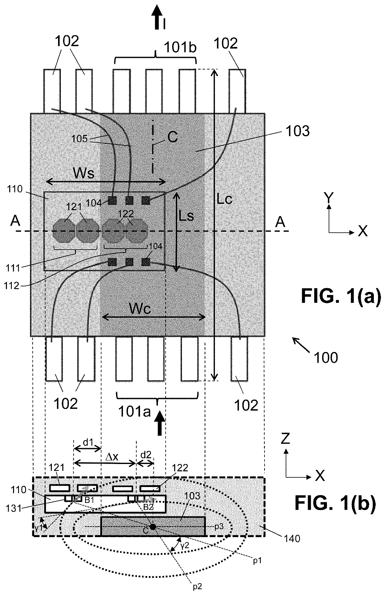
[0116]The present invention will be described with respect to particular embodiments and with reference to certain drawings, but the invention is not limited thereto but only by the claims. The drawings described are only schematic and are non-limiting. In the drawings, the size of some of the elements may be exaggerated and not drawn on scale for illustrative purposes. The dimensions and the relative dimensions do not correspond to actual reductions to practice of the invention.

[0117]Furthermore, the terms first, second and the like in the description and in the claims, are used for distinguishing between similar elements and not necessarily for describing a sequence, either temporally, spatially, in ranking or in any other manner. It is to be understood that the terms so used are interchangeable under appropriate circumstances and that the embodiments of the invention described herein are capable of operation in other sequences than described or illustrated herein.

[0118]Moreover, ...


PUM


Abstract

A current sensor device for measuring a current of at least 30 Amps, comprising: a leadframe with a electrical conductor having a centerline; a substrate mounted to the electrical conductor and comprising a first and a second magnetic sensor configured for providing a first and second value; and a processing circuit for determining the current based on a difference or weighted difference between the first and second value. The first and second magnetic sensor are arranged asymmetrically with respect to the centerline.

Description

FIELD OF THE INVENTION[0001]The present invention relates in general to the field of current sensors, and more in particular current sensors capable of measuring a relatively high current (e.g. at least 30 Amps).BACKGROUND OF THE INVENTION[0002]Current sensors based on magnetic sensors for measuring relatively high currents (e.g. at least 25 Amps) exist. They typically measure a current flowing in an external conductor. A problem of such a current sensor system is that the accuracy of the measurement largely depends on the mounting tolerances of the sensor device relative to the electrical conductor. While it is possible to increase accuracy by performing a calibration test at system level (e.g. after the sensor chip is mounted on a PCB), this is highly inconvenient, subject to human error, time consuming and costly.[0003]There is always room for improvements or alternatives.SUMMARY OF THE INVENTION[0004]It is an object of embodiments of the present invention to provide a current se...

Claims


Application Information

Patent Timeline
IPC IPC(8): G01R15/20G01R19/00G01R19/32
CPCG01R19/32G01R19/0092G01R15/207G01R15/202G01R15/20G01R15/205G01R19/25G01R33/0005G01R33/072G01R33/091G01R33/0094G01R33/0011
Inventor BILBAO DE MENDIZABAL, JAVIERHOUIS, SIMON
Owner MELEXIS TECH NV
Why Eureka
Try Eureka