Screen printer

a screen printer and printer technology, applied in the field of screen printers, can solve the problems of printing errors, long time-consuming operation, and problems such as the inability to print, and achieve the effect of improving the printing process

Active Publication Date: 2020-06-18
FUJI MASCH MFG CO LTD
View PDF0 Cites 0 Cited by
  • Summary
  • Abstract
  • Description
  • Claims
  • Application Information

AI Technical Summary

Benefits of technology

The patent describes a configuration where a standby printing processing section raises a board from below and makes contact with a stencil, while filling pattern holes with solder paste. The board then lowers to separate from the stencil based on a board conveyance signal. This configuration prevents the solder from drying and improves print processing, even if there is a long time between the printing of different boards. The technical effect of this patent text is to improve print processing efficiency and prevent the solder from drying during standby printing processing.

Problems solved by technology

Here, if the solder paste is not appropriately applied onto the board, problems may occur in a subsequent process of mounting electronic components.
For example, with a screen printer, there are cases in which operation is stopped for a long period of time due to components running out at a component mounter or the like.
The residual solder becomes more viscous when left in the pattern hole for an extended period of time, which causes problems such as preventing the pattern hole pattern from being filled with new solder paste, thereby leading to printing errors.

Method used


Image

  • Screen printer
  • Screen printer
  • Screen printer

Examples


Embodiment Construction

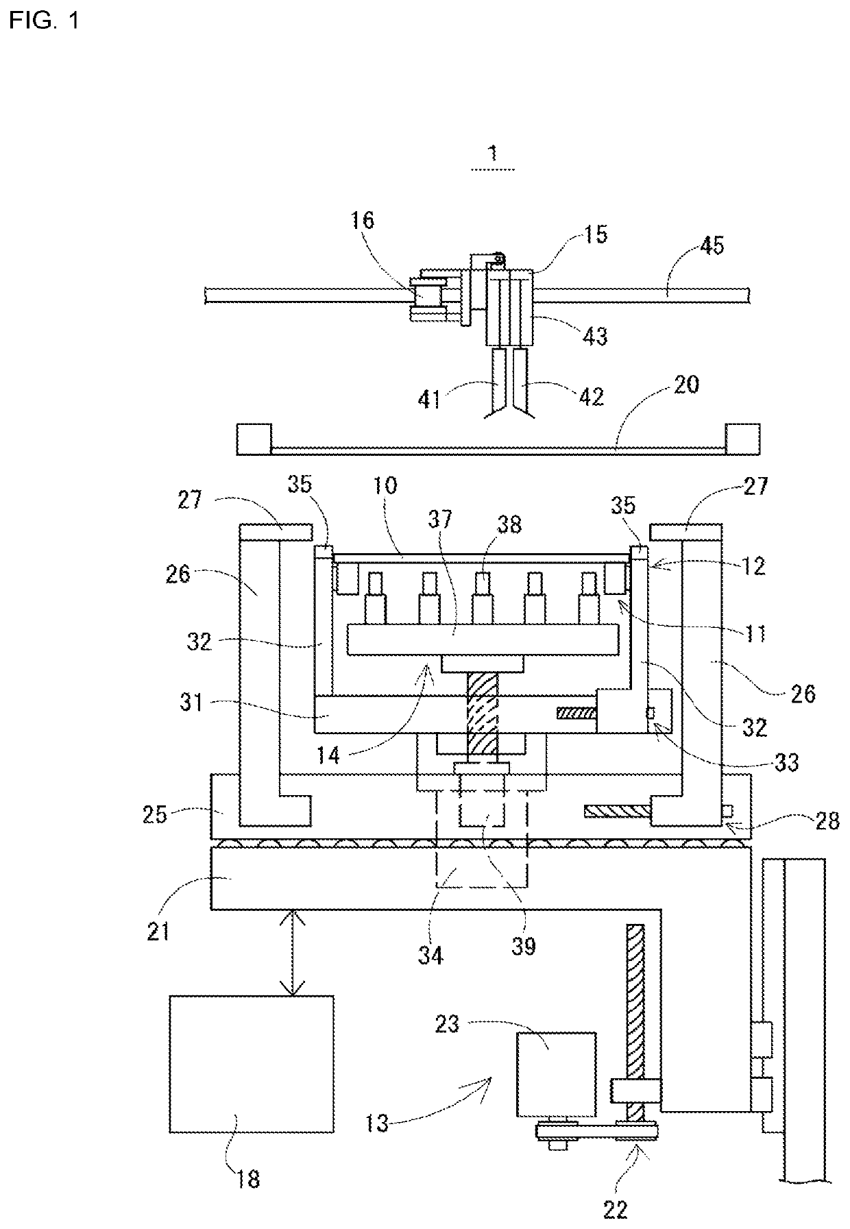
[0014]Hereinafter, an embodiment of the present disclosure of a screen printer will be described with reference to the figures. FIG. 1 shows an internal configuration of an embodiment of a screen printer. Screen printer 1 constitutes a board production line together with an inspection machine, a component mounter, and the like. Thus, a board on which solder paste has been printed is conveyed to a subsequent process, then, at a downstream side, the print condition is inspected, electronic components are mounted, and the like. Screen printer 1 is covered by a main body cover, and by opening an opening / closing cover, it is possible to perform changeover such as stencil replacement and maintenance and the like in the main body.

[0015]The internal configuration of the screen printer shown in FIG. 1 is assembled in the main body. With screen printer 1, stencil 20 is attached via a stencil holder, and board 10 is conveyed below the stencil in the width direction of the main body (the direct...


PUM


Abstract

A screen printer comprising: a conveyance device configured to convey a board; a board holding device configured to position a conveyed board at a printing position; a stencil holding device configured to attach a stencil above the held board; a squeegee device configured to fill pattern holes of the stencil with solder paste; a board raising and lowering device configured to raise and lower the board positioned by the board holding device; and a control device configured to perform drive control of each the above devices, the control device including a standby printing processing section configured to raise the board from below with respect to the stencil such that the board contacts the stencil, stand by in a state with solder paste filled in the pattern holes, and lower the board to separate the board from the stencil in accordance with a board conveyance signal.

Description

TECHNICAL FIELD[0001]The present application relates to a screen printer for improving print processing of solder paste onto a board via a stencil.BACKGROUND ART[0002]In a screen printer, a stencil is provided in which is formed a printing pattern made up of multiple pattern holes, and solder paste is spread over the stencil below which is a board. Printing onto the board is performed in the printing pattern by the solder paste that fills the pattern holes being applied to the board. Here, if the solder paste is not appropriately applied onto the board, problems may occur in a subsequent process of mounting electronic components. Thus, patent literature 1 below discloses a screen printer for preventing printing errors such as smearing or streaking of solder paste.[0003]For example, with a screen printer, there are cases in which operation is stopped for a long period of time due to components running out at a component mounter or the like. However, the solder paste filled in the pat...

Claims


Application Information

Patent Timeline
Patent Type & Authority Applications(United States)
IPC IPC(8): H05K3/12H05K3/00B41F15/18B41F15/44
CPCB41F15/18H05K3/0085H05K2203/0139B41F15/44H05K3/1225B41M1/12B41F15/0881B41P2215/50H05K3/1233H05K3/3485
Inventor TORII, ATSUSHIFURUICHI, AKIRA
Owner FUJI MASCH MFG CO LTD
Why Eureka
Try Eureka