
Method and device for scanning a solid angle

Active Publication Date: 2020-07-02
ROBERT BOSCH GMBH
View PDF3 Cites 0 Cited by
  • Summary
  • Abstract
  • Description
  • Claims
  • Application Information

AI Technical Summary

Benefits of technology

The patent describes a method for improving the measurement rate of a scanner or LIDAR device by at least doubling the measuring points per rotation or angle range. This may be done by generating an electromagnetic beam, such as a laser or LED, and dividing it into multiple partial beams with different solid angles. The resulting overexposure of adjoining detector elements is reduced, and the incident contact points of the received beams are spatially at a great distance from one another. Additionally, the mirror used in the device may be pivoted orthogonally with regards to the rotation axis, which simplifies the design and operation of the device. The advantage of the patent is to increase the scanning frequency or horizontal angle without sacrificing vertical angle or resolution.

Problems solved by technology

Therefore, the overexposure of one detector element cannot or may only to a limited extent result in an overexposure of adjoining detector elements.

Method used


Image

  • Method and device for scanning a solid angle
  • Method and device for scanning a solid angle
  • Method and device for scanning a solid angle

Examples


Embodiment Construction

[0025]In the figures, the same constructive elements have the same reference numerals in each case.

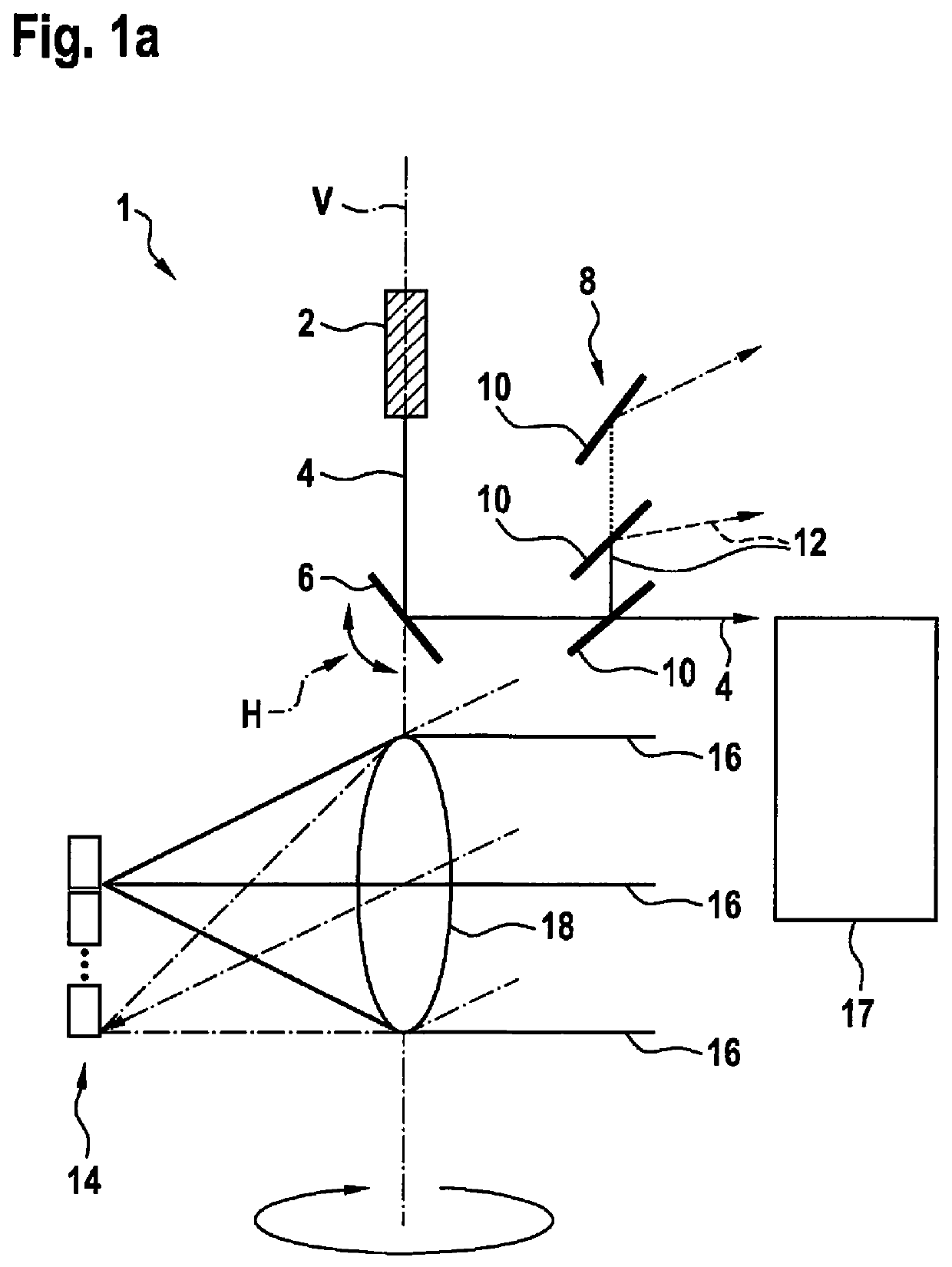
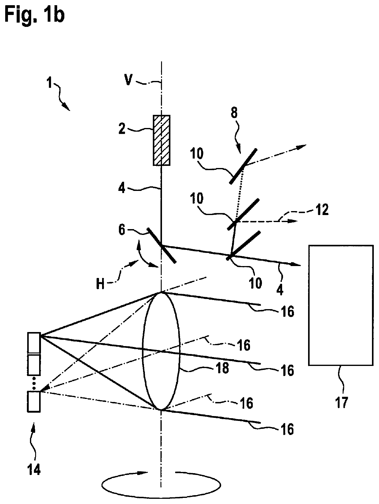
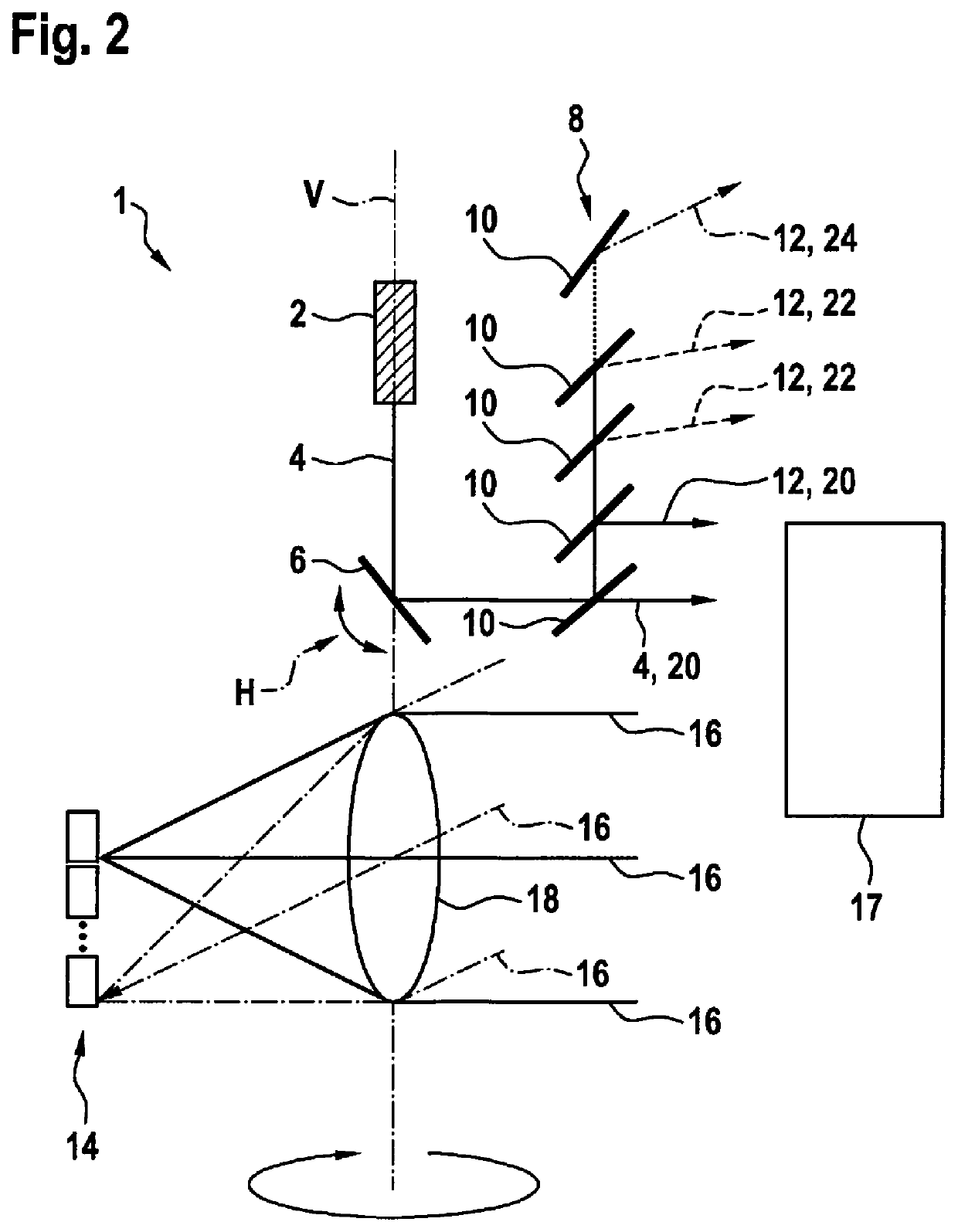
[0026]FIGS. 1a and 1b show a first exemplary embodiment of a LIDAR device 1. LIDAR device 1 includes a beam source 2, which is a laser 2 according to the first exemplary embodiment. Laser 2 is situated in device 1 in a steady-state manner and generates an electromagnetic beam 4. Generated beam 4 runs vertically from laser 2 to a mirror 6 and defines a vertical rotation axis V of device 1. Mirror 6 is situated in device 1 in such a way that vertical rotation axis V runs centrally through mirror 6. Mirror 6 reflects generated beam 4 and deflects beam 4 into a defined direction. Mirror 6 is rotatably mounted along rotation axis V and may, for example, rotate or pivot freely in an arbitrarily defined range. During a rotation, mirror 6 performs an uninterrupted movement that is directed into a direction of rotation. During a pivoting process, the mirror changes its direction of pivoting or ...


PUM


Abstract

A method for scanning solid angles is provided using at least two electromagnetic beams, at least one electromagnetic beam being generated that is subsequently deflected along a horizontal angle and / or along a vertical angle with the aid of a rotatable mirror; the solid angles being scanned using the at least one electromagnetic beam; and at least one reflected electromagnetic beam being received, after being reflected off an object, by a receiving optics that is pivotable along the horizontal angle synchronously with the mirror. Furthermore, a LIDAR device for carrying out the method is provided.

Description

FIELD[0001]Method for scanning a solid angle using at least one electromagnetic beam as well as a LIDAR deviceBACKGROUND INFORMATION[0002]Some conventional rotating 3D scanners are operated according to the LIDAR (light detection and ranging) principle. In this case, a laser beam is usually deflected in a meandering manner, so that a solid angle may be scanned. In order to deflect along a vertically running rotation axis, an additional deflection of the laser beam is also added along a horizontal rotation axis or pivoting axis. The laser beam is usually deflected in a line-shaped manner in such a way that the entire solid angle is scanned having a defined resolution. The distance between the scanning paths of the laser beam is particularly decisive. A compromise must thus be made between the resolution and a scanning frequency of a device of this type. In order to cover the gaps between the scanning paths of the laser beam and to increase the resolution capacity of a 3D scanner, an ...

Claims


Application Information

Patent Timeline
IPC IPC(8): G01S7/481G02B26/10G02B27/14G01S17/10G02B26/08
CPCG02B26/0816G01S17/10G02B27/144G01S7/4816G01S7/4817G01S7/4815G02B26/101G01S17/42G02B27/106
Inventor HOLLECZEK, ANNEMARIEBAIER, MATTHIASSCHNITZER, REINERHAS, REMIGIUSBOGATSCHER, SIEGWART
Owner ROBERT BOSCH GMBH
Learn More