Method for determining the location of an ego-vehicle

a technology for determining the location of an ego-vehicle and a vehicle, which is applied in the direction of vehicle position/course/altitude control, process and machine control, instruments, etc., can solve the problems of uncertainty in the line information retrieved from the digital map, the difficulty of using map information for lateral control, etc., and achieve the reduction of the weight of the measured state vector, and the effect of increasing the weight of the predicted state vector

Inactive Publication Date: 2020-07-09
VISTEON GLOBAL TECH INC
View PDF0 Cites 13 Cited by
  • Summary
  • Abstract
  • Description
  • Claims
  • Application Information

AI Technical Summary

Benefits of technology

[0010]The measured state vector may be calculated by an internal image processor of the ego-vehicle using image processing methods. Alternatively, the ego-vehicle may transmit the road sensor data to a server for image processing and receive the resulting parameters and / or state vector from the server. For this purpose the ego-vehicle may comprise a communication module for communicating wirelessly with the server. Outsourcing the process of image processing to a server may have the advantage, that processing power is not limited by the resources available in the ego-vehicle. Moreover, improvements to image processing algorithms can be implemented without having to provide software update to the ego-vehicle.
[0031]According to an aspect, the information processing device further comprises a location module for providing current location information based on sensor data obtained from at least one location sensor of the ego-vehicle. The at least one location sensor may receive location data from a Global Navigation Satellite System (GNSS). Furthermore, the at least one sensor may comprise an Inertial Measurement Unit (IMU). Data obtained from the GNSS and the IMU may be combined by the location module in order to improve the location accuracy. The location information provided by the location module may be used in order to localize the ego-vehicle on a HD map.

Problems solved by technology

Using map information for lateral control is more difficult, as the quality of the information derived from the map heavily depends on the precision of the positional and heading information of the ego-vehicle.
Uncertainty in the ego-vehicle position and pose directly results in uncertainty in the line information retrieved from the digital map.

Method used


Image

  • Method for determining the location of an ego-vehicle
  • Method for determining the location of an ego-vehicle
  • Method for determining the location of an ego-vehicle

Examples


Embodiment Construction

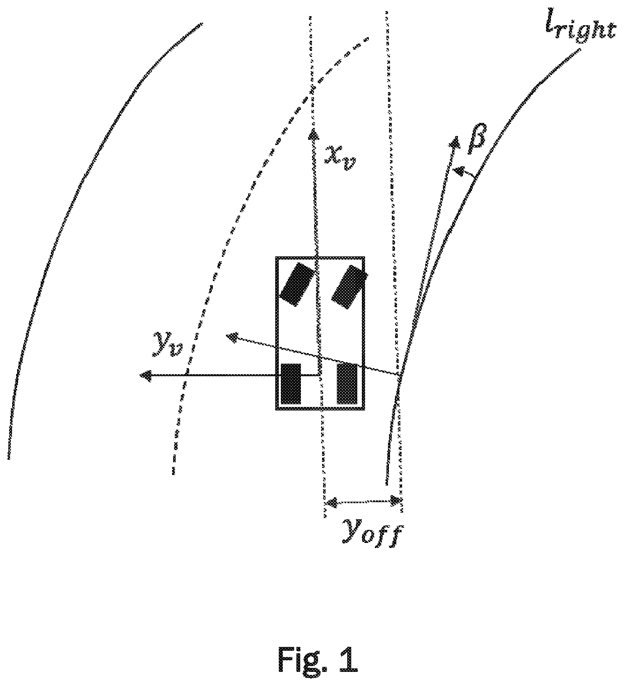
[0037]FIG. 1 is a schematic top view of a vehicle EV (i.e., the ego-vehicle) travelling along the right lane of a road. The position of the ego-vehicle with respect to the right lane boundary lright is described by a four-dimensional state vector

X=(yoffβc0c1),

wherein yoff describes the offset between a reference point of the ego-vehicle to the lane boundary, β describes the angle between the right lane boundary and the ego-vehicle's movement (i.e. the heading of the ego-vehicle), c0 describes the curvature of the lane boundary, and c1 describes the rate of change (first derivative) of c0.

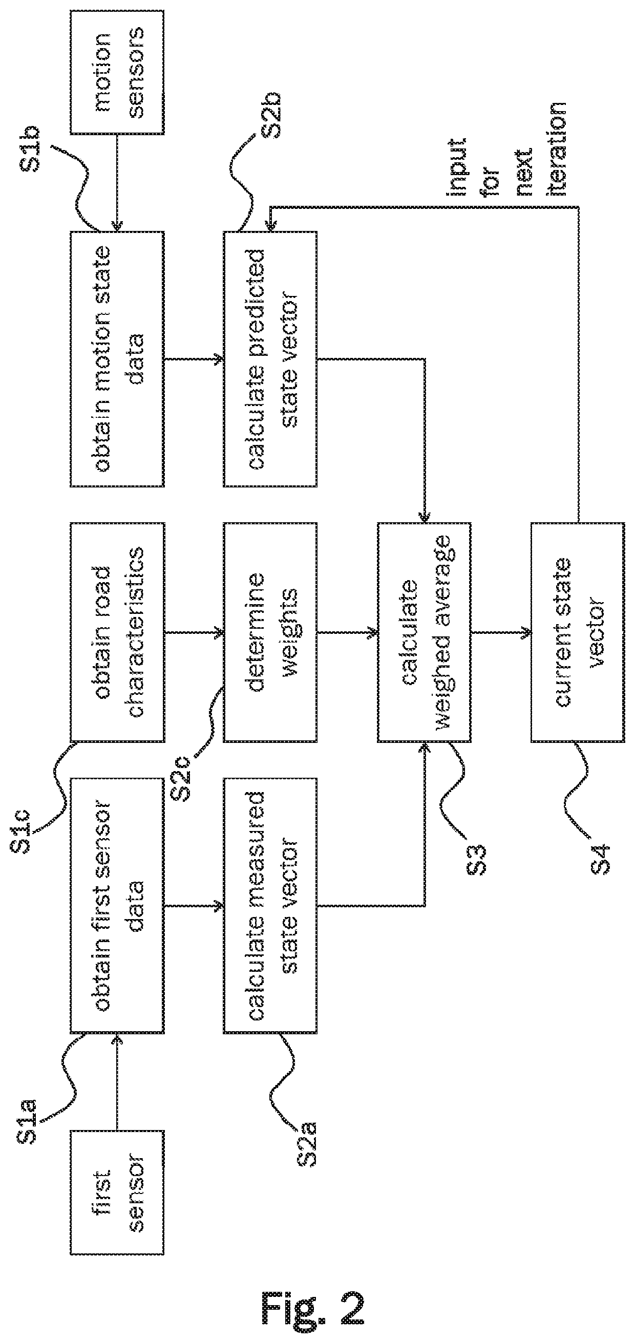
[0038]FIG. 2 shows a process flow schematically illustrating a method according to an embodiment. This method may be executed by an information processing device of an ego-vehicle.

[0039]In a step S1a, first sensor data is obtained from a first road sensor of the ego-vehicle. The ego-vehicle may comprise more than one road sensor. Accordingly, second sensor data, third sensor data, and / or fourth sens...


PUM


Abstract

A method for determining a current state vector describing location and heading of an ego-vehicle with respect to a lane boundary of a road comprises a step of obtaining road sensor data from at least one road sensor of the ego-vehicle detecting the lane boundaries of the road. In another step, a measured state vector of the ego-vehicle is calculated from the road sensor data. Furthermore, motion state data related to current heading and velocity of the ego-vehicle is obtained and a predicted state vector of the ego-vehicle is calculated based on the motion state data of the ego-vehicle and a previous state vector of the ego-vehicle. Finally a current state vector is determined by calculating a weighted average of the measured state vector and the predicted state vector of the ego-vehicle. The weights are determined based on characteristics of an upcoming section of the road.

Description

CROSS-REFERENCES TO RELATED APPLICATIONS[0001]This patent application claims priority to European Patent Application Serial No. 19150772.2, filed Jan. 8, 2019 which is incorporated herein by reference in its entirety.TECHNICAL FIELD[0002]One or more embodiments described herein relate to a method for determining the location of an ego-vehicle. In particular, a method for determining a current state vector describing location and heading of an ego-vehicle with respect to a lane boundary of a road is described. Furthermore, one or more embodiments described herein relate to an information processing device for determining a current state vector describing location and heading of an ego-vehicle with respect to a lane boundary of a road.BACKGROUND[0003]Modern road vehicles may be equipped with a large amount of sensors to perceive their environment. Sensors such as cameras, LiDARs or radars may be used to detect objects around a vehicle as well as road surface markings defining lane bou...

Claims


Application Information

Patent Timeline
Patent Type & Authority Applications(United States)
IPC IPC(8): B60W40/072G06K9/00G05D1/02
CPCB60W2520/06G05D2201/0213G06K9/00798G05D1/0276G05D1/0287B60W40/072B60W2556/45G08G1/0104G08G1/052G08G1/096805G08G1/167G05D1/0231G05D1/0257G05D1/027G05D1/0278G05D1/021B60W40/10B60W2520/10B60W2520/00B60W2554/805B60W2552/30B60W2556/50B60W50/0097B60W2050/0025B60W2420/52B60W2420/42B60W30/10B60W2552/53G06V20/588
Inventor OTTO, MATHIASPFEIFLE, MARTINKARAMANOV, NIKOLA
Owner VISTEON GLOBAL TECH INC
Why Eureka
Try Eureka