
Compound angle bearing assembly

a technology of bearing assembly and compound angle, which is applied in the direction of sealing/packing, directional drilling, and borehole/well accessories, etc., can solve the problem of limiting the ability to operate the drill string in rotary mode, and achieve the effect of extending the control piston and preventing fluid communication

Active Publication Date: 2020-07-09
TURBO DRILL IND INC
View PDF0 Cites 0 Cited by
  • Summary
  • Abstract
  • Description
  • Claims
  • Application Information

AI Technical Summary

Benefits of technology

Enables efficient directional drilling by reducing bit orbit diameter, increasing rotation speed, and maintaining toolface angle stability, thereby enhancing drilling efficiency and reducing side loading and cyclical fatigue.

Problems solved by technology

However, the introduced external angle may, for example and without limitation, limit the ability to operate the drill string in rotary mode because of the increased bit orbit diameter, increased friction, and increased vibration or shock on the drill string.

Method used


Image

  • Compound angle bearing assembly
  • Compound angle bearing assembly
  • Compound angle bearing assembly

Examples


Embodiment Construction

[0038]It is to be understood that the following disclosure provides many different embodiments, or examples, for implementing different features of various embodiments. Specific examples of components and arrangements are described below to simplify the present disclosure. These are, of course, merely examples and are not intended to be limiting. In addition, the present disclosure may repeat reference numerals and / or letters in the various examples. This repetition is for the purpose of simplicity and clarity and does not in itself dictate a relationship between the various embodiments and / or configurations discussed.

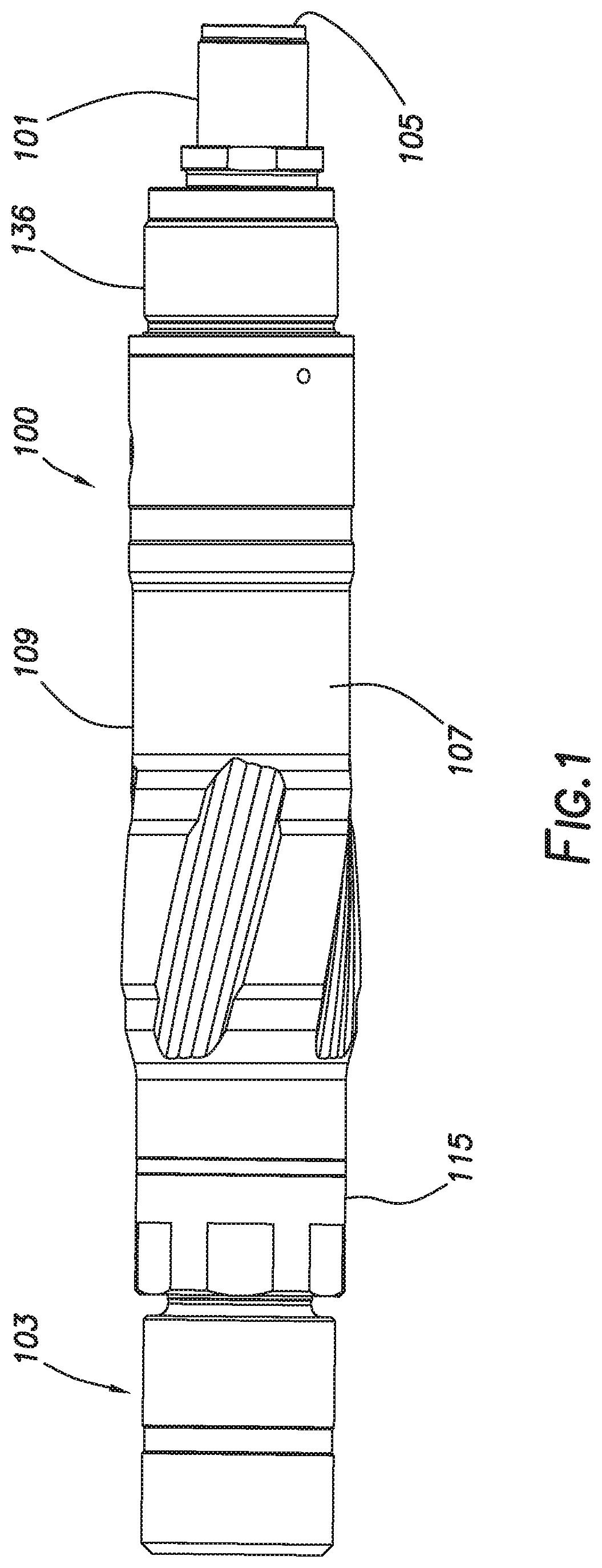
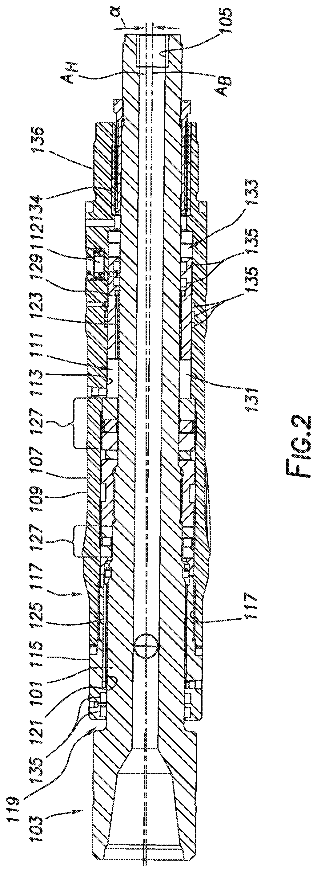
[0039]FIGS. 1, 2 depict bearing assembly 100 consistent with at least one embodiment of the present disclosure. Bearing assembly 100 may be used to couple driveshaft 101 to a power section of a drilling string for use in a wellbore. In some embodiments, driveshaft 101 may include bit box 103 positioned at a lower end of driveshaft 101. As used herein, the terms “upper”...


PUM


Abstract

A bearing housing for a bottomhole assembly of a downhole tool includes an upper bearing housing, lower bearing housing, and a driveshaft. The upper bearing housing and lower bearing housing include a bore defining a bore longitudinal axis. The outer surface of the upper bearing housing defining a bearing housing longitudinal axis, the bearing housing longitudinal axis formed at an angle to the bore longitudinal axis. The upper bearing housing may be formed by forming a bore through an upper bearing housing blank and subsequently forming the outer surface of the upper bearing housing concentric with the bearing housing longitudinal axis.

Description

CROSS-REFERENCE TO RELATED APPLICATIONS[0001]This application is a nonprovisional application that claims priority from U.S. provisional application No. 62 / 411,421, filed Oct. 21, 2016.TECHNICAL FIELDField of the Disclosure[0002]The present disclosure relates generally to bearing assemblies, and specifically to bearing assemblies for directional drilling.Background of the Disclosure[0003]When drilling a wellbore, the drill bit may be turned by a rotation of the drill string or by a downhole motor. The downhole motor may be used to rotate the drill bit while the drill string is stationary. In such a drill string, the bottom hole assembly (BHA), located at the end of the drill string, may include the downhole motor, the drill bit, and a bearing section. The bearing section couples between the motor sub and the drill bit and houses the drive shaft which couples between the drill bit and the downhole motor. The bearing section couples to the drive shaft through one or more bearings to a...

Claims


Application Information

Patent Timeline
Patent Type & Authority Applications(United States)
IPC IPC(8): E21B4/00E21B7/06E21B17/10F16C35/02F16C35/04E21B34/12F16C25/08
CPCF16C17/02E21B4/003F16C2240/30F16C17/04E21B7/067F16C33/26F16C25/08E21B34/12E21B7/062E21B17/1014F16C35/042F16C19/54F16C35/02F16C2352/00
Inventor RITCHIE, SHELDONFEDDEMA, CHAD
Owner TURBO DRILL IND INC
Features
  • Generate Ideas
  • Intellectual Property
  • Life Sciences
  • Materials
  • Tech Scout
  • Unparalleled Data Quality
  • Higher Quality Content
  • 60% Fewer Hallucinations
Learn More