Downhole oil, gas, water and sand separation method and separator

a separation method and oil sand technology, applied in the direction of sealing/packing, fluid removal, borehole/well accessories, etc., can solve the problems that the downhole oil-water or gas-water separation device cannot effectively achieve the oil-water or gas-water separation, and achieve the separation of oil drops or bubbles. , the effect of reducing the descending velocity of liquids

Active Publication Date: 2020-07-09
PETROCHINA CO LTD +1
View PDF0 Cites 6 Cited by
  • Summary
  • Abstract
  • Description
  • Claims
  • Application Information

AI Technical Summary

Benefits of technology

[0020]1. In the downhole oil, gas, water and sand separation method of the present disclosure, a plurality of accommodating cavities are designed in the flow direction of the produced liquid in the liquid outlet pipeline, so that the crude oil in the oil jacket annulus flows into the liquid outlet pipeline simultaneously through one of the liquid inlet hole groups corresponding to each of the accommodating cavities; and by using the plurality of accommodating cavities longitudinally distributed on the liquid outlet pipeline to share the flow rate of the crude oil in the oil jacket annulus in the whole wellbore, the descending velocity of the crude oil in each of the accommodating cavities can be decreased to 1 / N (N is the number of accommodating cavities) of the descending velocity of the crude oil at the liquid inlet in the oil jacket annulus of the conventional oil well, i.e. the relative floating velocity of the oil drops or bubbles in the crude oil is increased, thus finally achieving the purpose of an efficient separation of oil, gas and water.
[0021]In addition, the downhole oil, gas, water and sand separation method of the present disclosure can enable the sand in the high water-content crude oil to be discharged from the accommodating cavity through a plurality of sand outlet holes of the accommodating cavity, thus realizing the separation between sand and water.
[0022]Furthermore, the downhole oil, gas, water and sand separation method of the present disclosure can improve the separation velocity of the oil drops in the crude oil by providing a filter material box containing a porous medium in the accommodating cavity.
[0023]2. In the downhole oil, gas, water and sand separator of the present disclosure, a plurality of settling cups are provided in an axial direction of the liquid outlet pipeline, each corresponding to one of the liquid inlet hole groups on the liquid outlet pipeline; the total amount of the crude oil in the whole oil jacket annulus is shared by the plurality of settling cups, so that the crude oil in the oil jacket annulus is divided into a plurality of parts, thus achieving the purposes of decreasing the descending velocity of the liquid in each of the settling cups and promoting the separation of the oil drops or bubbles from the water.

Problems solved by technology

The existing downhole oil-water or gas-water separation device cannot effectively achieve the oil-water or gas-water separation and exploitation in the high water-content crude oil.

Method used


Image

  • Downhole oil, gas, water and sand separation method and separator
  • Downhole oil, gas, water and sand separation method and separator
  • Downhole oil, gas, water and sand separation method and separator

Examples


embodiment 1

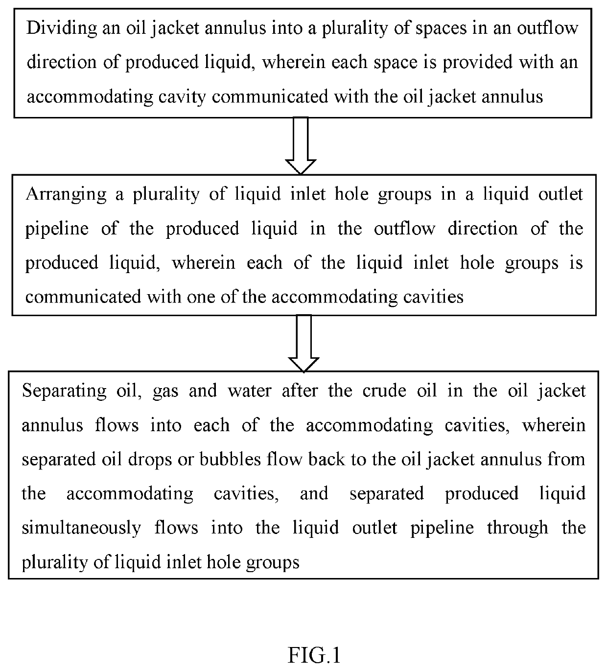
[0039]As illustrated in FIG. 1, the present disclosure provides a downhole oil, gas, water and sand separation method, comprising:

[0040]step 1: dividing an oil jacket annulus into a plurality of spaces in an outflow direction of produced liquid, wherein each of the spaces is provided with an accommodating cavity communicated with the oil jacket annulus, so that crude oil in the oil jacket annulus is divided into a plurality of parts which flow into a plurality of accommodating cavities, respectively, a descending velocity of liquid in crude oil in each of the accommodating cavities is decreased relative to a descending velocity of liquid in the crude oil in the oil jacket annulus, and an ascending velocity of oil drops or bubbles in the crude oil in each of the accommodating cavities is increased relative to an ascending velocity of oil drops or bubbles in the crude oil in the oil jacket annulus;

[0041]step 2: arranging a plurality of liquid inlet hole groups in a liquid outlet pipel...

embodiment 2

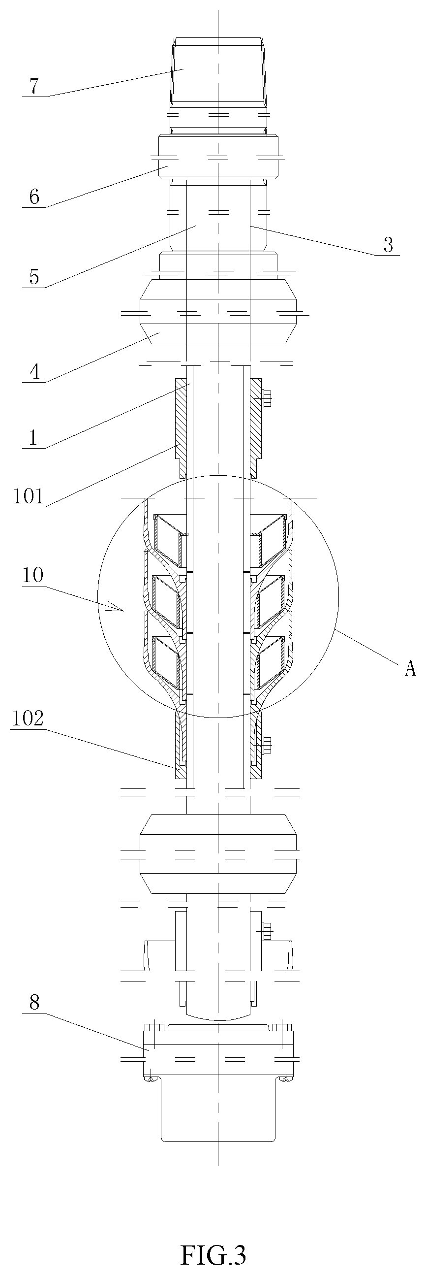
[0080]As illustrated in FIGS. 3 to 7, the present disclosure further provides a downhole oil, gas, water and sand separator 10, which is designed using the downhole oil, gas, water and sand separation method of Embodiment 1. Of course, separators of other structures can also be designed according to the downhole oil, gas, water and sand separation method of Embodiment 1. The separator 10 of Embodiment 2 is only one specific example, and any other separator of the similar structure designed by a person skilled in the art according to the example of Embodiment 2 shall fall within the scope of the embodiments of the present disclosure.

[0081]The downhole oil, gas, water and sand separator 10 comprises a liquid outlet pipeline 1 and a plurality of settling cups 2, wherein the liquid outlet pipeline 1 is provided therein with a plurality of liquid inlet hole groups 11 spaced apart in an axial direction thereof; and the plurality of settling cups 2 are connected to each other to be dispose...


PUM


Abstract

A downhole oil, gas, water and sand separation method and separator (10). The downhole oil, gas, water and sand separation method comprises: step 1: dividing an oil jacket annulus into a plurality of spaces in an outflow direction of produced liquid, wherein each space is provided with an accommodating cavity (21) communicated with the oil jacket annulus; step 2: arranging a plurality of liquid inlet hole groups (11) in a liquid outlet pipeline (1) of the produced liquid in the outflow direction of the produced liquid, wherein each of the liquid inlet hole groups (11) is communicated with one of the accommodating cavities (21); and step 3: separating oil, gas and water after the crude oil in the oil jacket annulus flows into each of the accommodating cavities (21), wherein separated oil drops or bubbles flow back to the oil jacket annulus from the accommodating cavities (21), and separated produced liquid simultaneously flows into the liquid outlet pipeline (1) through the plurality of liquid inlet hole groups (11). The downhole oil, gas, water and sand separation method and separator can realize a rapid downhole oil-water or gas-water separation in the high water-content crude oil.

Description

TECHNICAL FIELD[0001]The present disclosure relates to a separation method and a separator, in particular to a downhole oil, gas, water and sand separation method and a separator applied in the field of oil field development.BACKGROUND ART[0002]As the oil fields enter the high water-content production period, the emerging single well integral injection and production technique, and the gas-liquid separation technique needed to improve the pump efficiency, both require an efficient downhole oil-water or gas-water separation technique.[0003]The existing downhole oil-water or gas-water separation device cannot effectively achieve the oil-water or gas-water separation and exploitation in the high water-content crude oil.SUMMARY OF THE DISCLOSURE[0004]An object of the present disclosure is to provide a downhole oil, gas, water and sand separation method, through which a downhole oil-water or gas-water separation can be rapidly performed in the high water-content crude oil.[0005]Another o...

Claims


Application Information

Patent Timeline
Patent Type & Authority Applications(United States)
IPC IPC(8): E21B43/38E21B43/08
CPCE21B43/38E21B43/08E21B43/121E21B43/34E21B33/126E21B43/35
Inventor WANG, YANWANG, DEMINZHONG, RONGLIU, QUANLIU, JINTANG
Owner PETROCHINA CO LTD
Why Eureka
Try Eureka