
Measurement system and method for multiple antenna measurements with different angles of arrival
a measurement system and antenna technology, applied in the direction of antennas, measurement instrument housings, electronic circuit testing, etc., can solve the problems of limiting the accuracy and functionality of testing methods and devices, and achieve the effects of enhancing efficiency, reducing complexity, and increasing efficiency
- Summary
- Abstract
- Description
- Claims
- Application Information
AI Technical Summary
Benefits of technology
Problems solved by technology
Method used
Image

Examples
Embodiment Construction
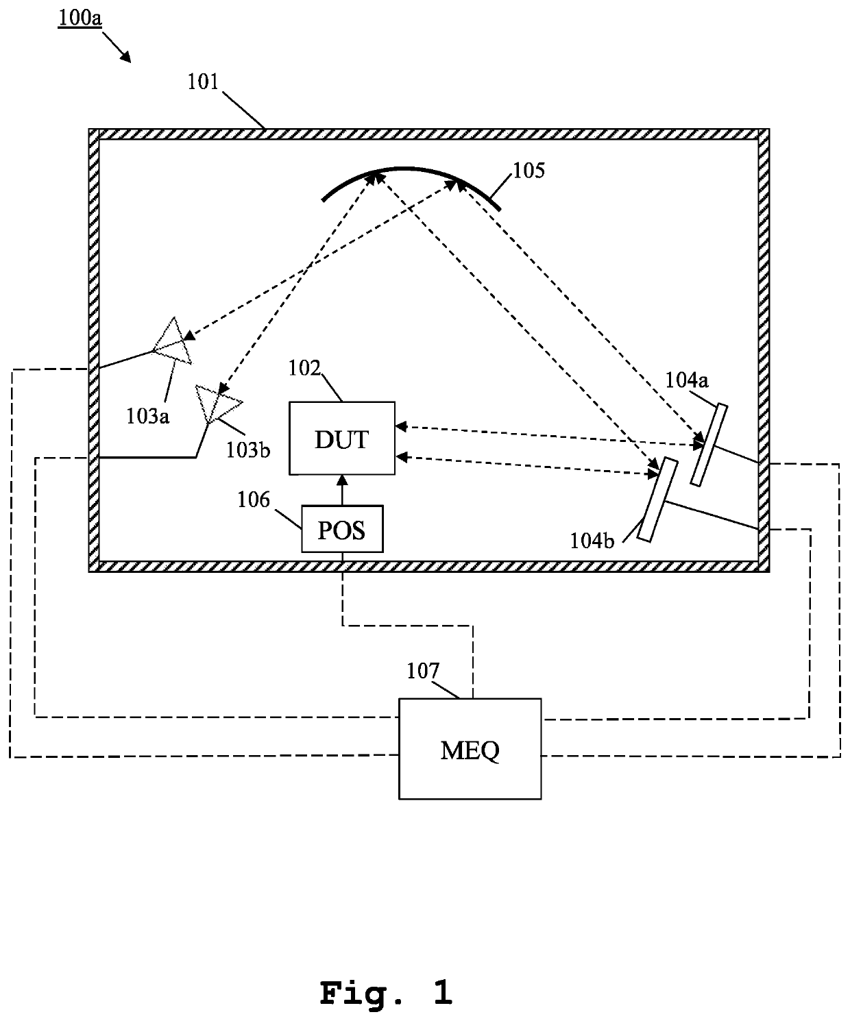
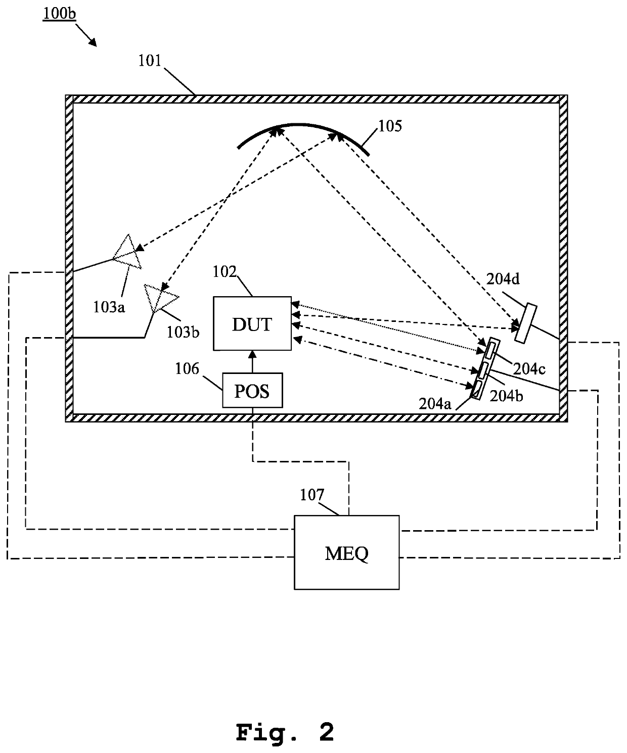
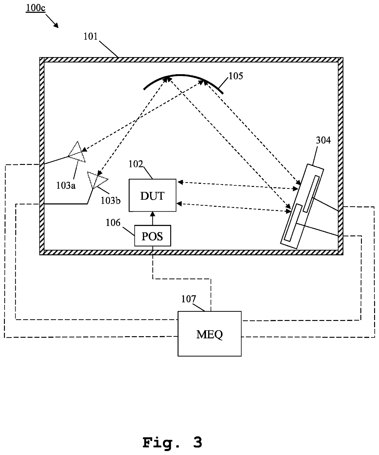
[0032]Firstly, FIG. 1 depicts an exemplary embodiment of an inventive measurement system 100a. The measurement system 100a comprises, inside an anechoic chamber 101, a device under test 102, several measurement antennas, exemplarily two measurement antennas 103a, 103b, several mirrors, exemplarily two mirrors 104a, 104b, at least one shaped reflector 105, and a positioner 106 for positioning the device under test 101.
[0033]In this exemplary case, each of the measurement antennas 103a, 103b is also a feed antenna. Furthermore, the shaped reflector 105 corresponds to a compact antenna test range reflector. In this context, it should be mentioned that if one of the several antennas corresponds to the normal compact antenna test range feed (CATR) antenna located at the focal point of the reflector, then the number of measurement antennas is the total number of antennas N but one, where N is a natural number, whereas if there is not a feed antenna located at the focal point of the reflec...
PUM
 Abstract
Description
Claims
Application Information