Power conversion system for nuclear power generators and related methods

a technology of power conversion system and nuclear power generator, which is applied in the direction of nuclear elements, greenhouse gas reduction, valves, etc., can solve the problems that conventional heat removal systems with complex networks of balance-of-plant components may not be suitable for use with these advanced reactor designs, and may require complex piping networks. to achieve the effect of effectively and efficiently removing heat from a nuclear core and eliminating a substantial amount of balance-of-plan

Active Publication Date: 2020-07-09
CARBON FREE HLDG LLC
View PDF1 Cites 2 Cited by
  • Summary
  • Abstract
  • Description
  • Claims
  • Application Information

AI Technical Summary

Benefits of technology

[0006]Therefore, various exemplary embodiments of the present disclosure may provide an improved power conversion system that can effectively and efficiently remove heat from a nuclear core while eliminating a substantial amount of balance-of-plant typically present in a conventional nuclear power generator.

Problems solved by technology

These heat transfer systems may require complex piping networks to connect the pressure vessel containing the nuclear core to heat exchangers generally located far away from the pressure vessel.
These systems are formed by components that are generally external to the pressure vessel containing the nuclear core and, therefore, result in a complex system of redundant piping, valves, and heat exchangers for passive systems with the addition of pumps / blowers and motive power managed and monitored by control systems and cabling.
While providing highly reliable heat source, however, these nuclear cores may be sealed within their pressurized vessels and, therefore, conventional heat removal systems with complex networks of balance-of-plant components may not be suitable for use with these advanced reactor designs.

Method used


Image

  • Power conversion system for nuclear power generators and related methods
  • Power conversion system for nuclear power generators and related methods
  • Power conversion system for nuclear power generators and related methods

Examples


Embodiment Construction

[0023]Reference will now be made in detail to the exemplary embodiments of the invention, examples of which are illustrated in the accompanying drawings. Wherever possible, the same reference numbers will be used throughout the drawings to refer to the same or like parts.

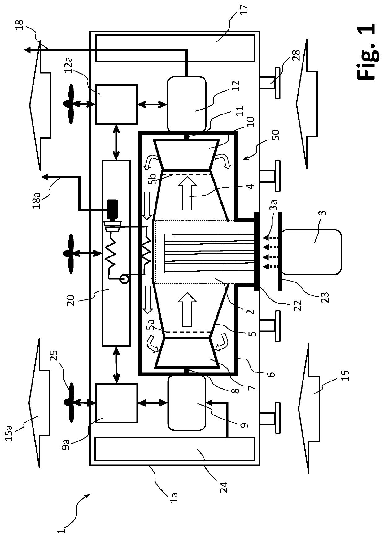
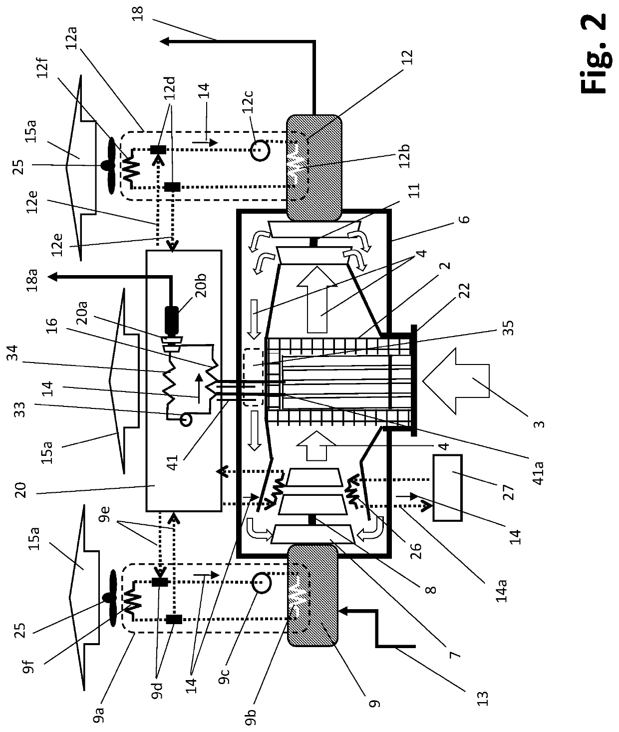
[0024]FIGS. 1 and 2 illustrate a power conversion system 1, according to one exemplary embodiment of the present disclosure. As shown in FIG. 1, power conversion system 1, consistent with the present disclosure, may be sufficiently compact to fit inside a transport container 1a (e.g., intermodal container), thereby making it easily transportable by any conventional transportation means, such as, for example, trucks, freight rails, and ships. Transport container 1a may include a plurality of pads 28 located at its bottom surface to provide a stable support platform from the ground. Pads 28 may be adjustable in height and may include a vibration dampening mechanism. Pads 28 also thermally separate the bottom portions ...


PUM


Abstract

Various exemplary embodiments of a power conversion system for converting thermal energy from a heat source to electricity are disclosed. In one exemplary embodiment, the power conversion system may include a substantially sealed chamber having an inner shroud having an inlet and an outlet and defining an internal passageway between the inlet and the outlet through which a working fluid passes. The sealed chamber may also include an outer shroud substantially surrounding the inner shroud, such that the working fluid exiting the outlet of the inner shroud returns to the inlet of the inner shroud in a closed-loop via a return passageway formed between an external surface of the inner shroud and an internal surface of the outer shroud. The power conversion system may further include a source heat exchanger disposed in the internal passageway of the inner shroud, the source heat exchanger being configured to at least partially receive a heat transmitting element.

Description

[0001]The application claims priority to U.S. Provisional Patent Application No. 62 / 552,532, filed Aug. 31, 2017, which is incorporated herein by reference in its entirety.TECHNICAL FIELD[0002]The present disclosure relates generally to nuclear power generators. In particular, various embodiments of the present disclosure relate to power conversion systems and methods for use in nuclear power generators.DESCRIPTION OF RELATED ART[0003]A nuclear power generator contains a nuclear core for producing thermal energy during normal operation. After shutdown, the nuclear core still produces decay heat, and the amount of decay heat after shutdown is generally proportional to the power generation history and power density of the nuclear core. To avoid overheating of the nuclear core after shutdown, decay heat energy must be transferred from the nuclear core by redundant heat transfer mechanisms, which are generally supplied by decay heat removal systems external to the nuclear core. These he...

Claims


Application Information

Patent Timeline
Patent Type & Authority Applications(United States)
IPC IPC(8): G21D1/00F22B37/00F02C1/05F02C1/10G21D1/02G21C15/24
CPCF02C1/05F02C1/10F22B37/002G21C15/24G21D1/02G21D1/006G21C1/00G21C5/02G21C13/02G21C15/04Y02E30/30Y02E30/00G21D7/00
Inventor FILIPPONE, CLAUDIO
Owner CARBON FREE HLDG LLC
Why Eureka
Try Eureka