Lubrication system

Inactive Publication Date: 2007-05-22
HANSEN INDAL TRANSMISSIONS
View PDF8 Cites 6 Cited by
  • Summary
  • Abstract
  • Description
  • Claims
  • Application Information

AI Technical Summary

Benefits of technology

[0004]The present invention seeks to provide a lubrication system and a lubricated assembly comprising a lubrication system in which potentially damaging contaminant p

Problems solved by technology

For dip or splash lubricated gear units, the factor can never become 1 because there is no possibility of effective filtration.
In the case of force lubricated gear units using a filter to improve cleanliness and reduce the contamination, significant expense is involved because micro filters must be used to get a good contamination factor approaching 1.
In contamina

Method used


Image

  • Lubrication system
  • Lubrication system
  • Lubrication system

Examples


Embodiment Construction

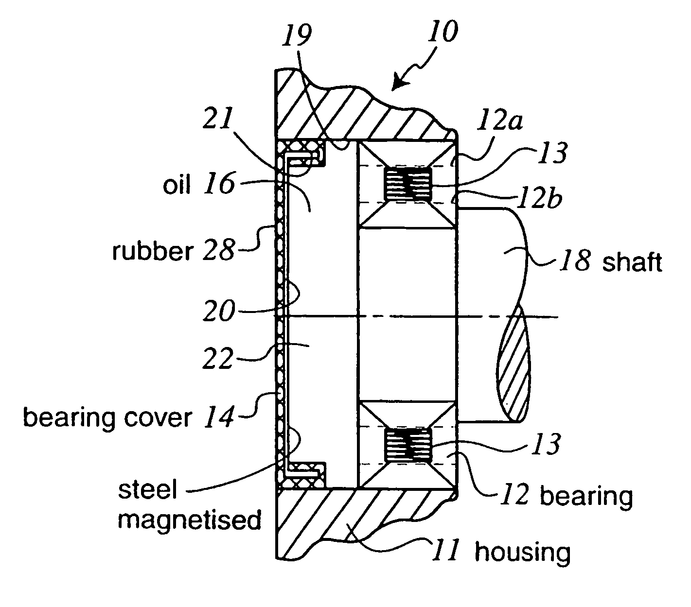
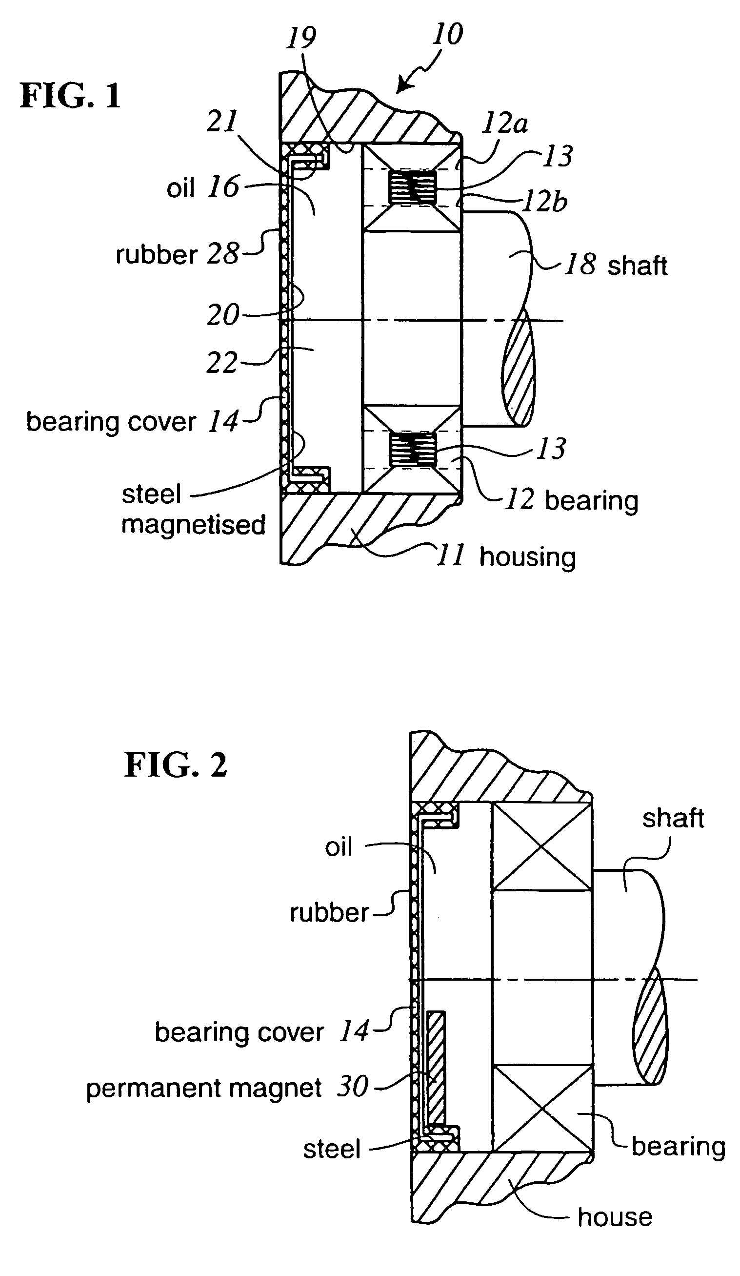
[0024]FIG. 1 shows part of a gear unit 10 having a housing outer wall 11 which supports a bearing 12 in which a shaft 18 is rotatably mounted. The bearing 12 is a roller bearing comprising rollers 13 which maintain spaced apart relatively rotatable inner and outer bearing contact surfaces12B, 12A.

[0025]The bearing 12 is located in a through-bore 19 in the housing wall whereby if necessary the bearing can be fitted or removed from externally of the gear unit. A bearing cover cap 14 fits tightly in the through-bore 19 and seals against leakage of the oil lubricant 16.

[0026]The bearing cover cap 14 is of a laminated construction comprising a magnetised steel cap having a central disc portion 20 and an axially inwardly extending flanged edge 21. The outer surface of the disk portion is provided with a rubber coating 28 which also extends over and encapsulates the flanged edge 21. Said rubber material assists in providing a fluid seal between the flanged edge of the cap and the through-b...


PUM

PropertyMeasurementUnit
Diameteraaaaaaaaaa
Magnetismaaaaaaaaaa

Abstract

A method for reducing the presence of ferritic particles in lubricant employed in the lubrication of rotary shaft bearing of the type that include a first bearing contact surface, a second bearing contact surface and a plurality of rotatable bearing members disposed therebetween, a lubrication system employing such method and a lubricated assembly. The method includes providing a ferritic particle collector element of magnetised material in close proximity to the bearing and a path of lubricant flowing to the bearing. The close proximity being within a distance from the bearing contact surface which is less than five times the maximum diameter of the bearing contact surfaces. The collecting element may be an existing component of a lubrication system or lubricated assembly which is rendered magnetic or may be a magnet or magnets secured to an existing component.

Description

BACKGROUND OF THE INVENTION[0001]This invention relates to a lubrication system and in particular, although not exclusively, to a lubrication system for a gear unit, and a gear unit comprising a lubrication system, wherein said gear unit comprises a plurality of rotatable components rotatably supported by rotary shaft bearings such as ball bearings or roller bearings.[0002]In a gear unit, as well as other types of lubricated equipment, the cleanliness of the oil is one of the most important factors influencing the life time of the bearings. In a method of bearing calculation according to ISO 281 standard, and in combination with a service life factor (axyz) dependent on load and contamination, the factor for the contamination varies from 0 to 1. For dip or splash lubricated gear units, the factor can never become 1 because there is no possibility of effective filtration. In the case of force lubricated gear units using a filter to improve cleanliness and reduce the contamination, si...

Claims


Application Information

Patent Timeline
IPC IPC(8): B01D35/06B03C1/30F01M11/03F16C33/66F16H57/04F16N39/06
CPCB03C1/30F16C33/667F16C33/723F16C33/76F16H57/042F16N39/06F01M2001/1042F16H57/0404F16H57/0423F16H57/045F16C2361/61
Inventor LEIMANN, DIRK-OLAF
Owner HANSEN INDAL TRANSMISSIONS
Why Eureka
Try Eureka