Subjective optometry apparatus

a subject-oriented optometry and apparatus technology, applied in the field of subject-oriented optometry apparatus, can solve the problem that the target light flux cannot be excellently projected onto the subject eye, and achieve the effect of high-quality subjective examination

Active Publication Date: 2020-07-16
NIDEK CO LTD
View PDF0 Cites 0 Cited by
  • Summary
  • Abstract
  • Description
  • Claims
  • Application Information

AI Technical Summary

Benefits of technology

[0005]In view of the above-described related art, an object of the present disclosure is to provide a subjective optometry apparatus cap...

Problems solved by technology

However, due to space saving, there is a problem regarding distortion of a visual target image and a problem that a target light...

Method used


Image

  • Subjective optometry apparatus
  • Subjective optometry apparatus
  • Subjective optometry apparatus

Examples


example

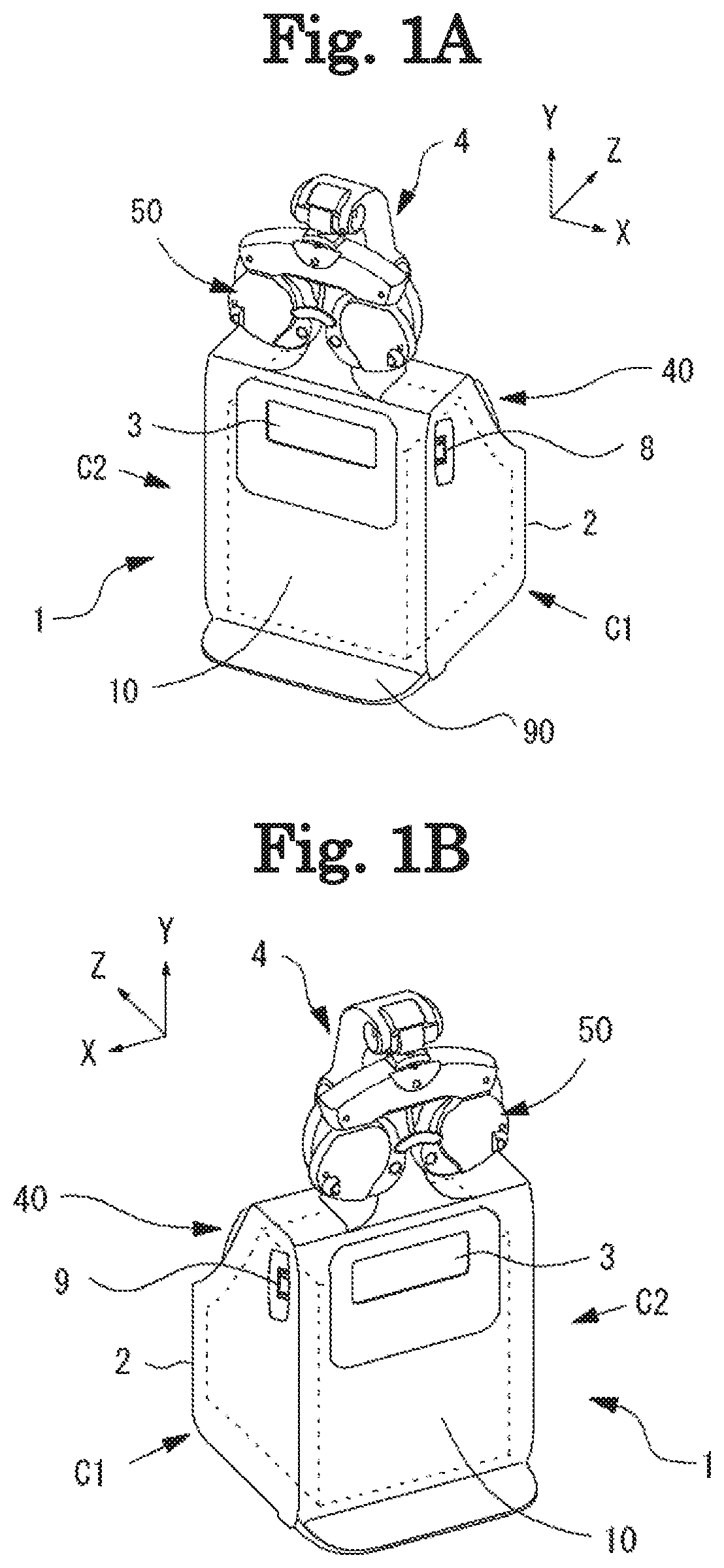
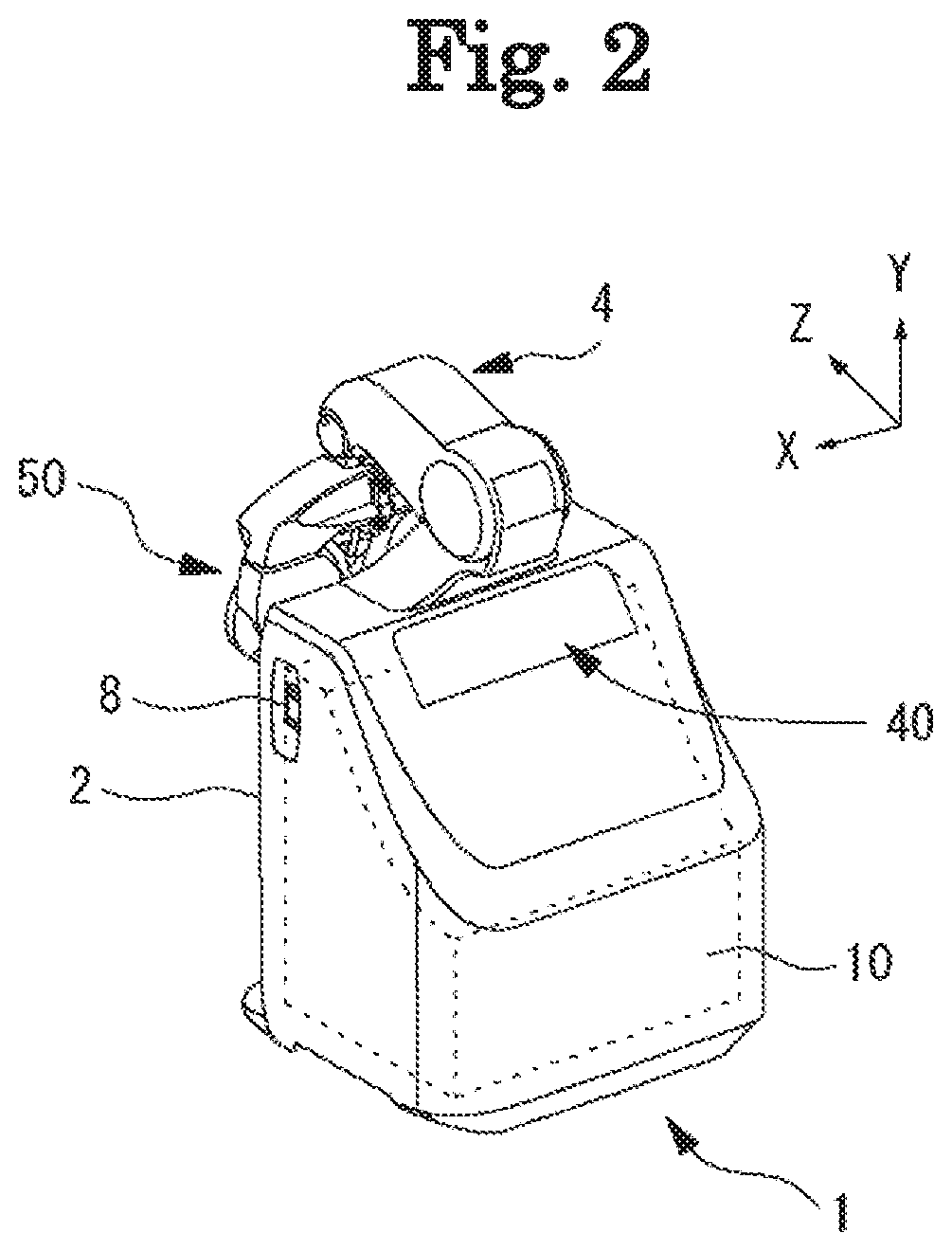
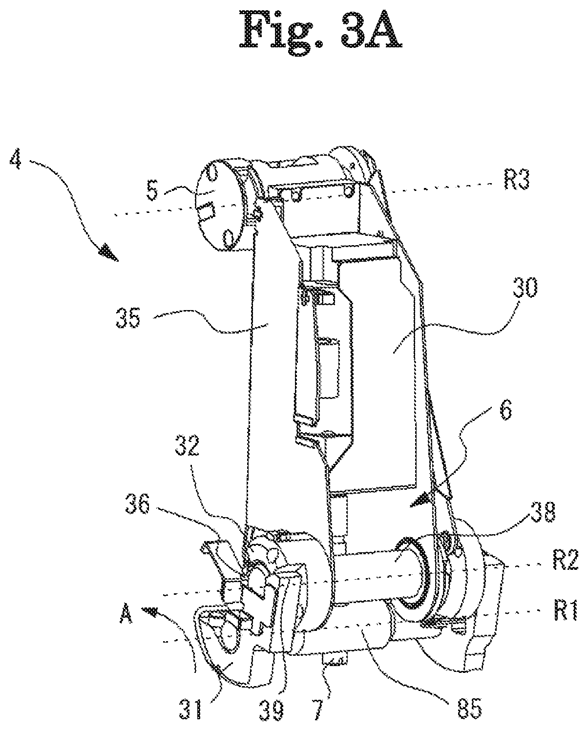
[0056]Hereinafter, the configuration of the subjective optometry apparatus in the present example will be described. For example, FIGS. 1A and 1B are perspective views illustrating the subjective optometry apparatus 1 from a front side. For example, FIG. 2 is a perspective view illustrating the subjective optometry apparatus 1 according to the present example from a rear surface side. In addition, in the present example, the side on which the presentation window 3 which will be described later is positioned will be described as the front surface of the subjective optometry apparatus 1, and the side on which an observation window 41 which will be described later is positioned will be described as the rear surface of the subjective optometry apparatus 1. For example, FIG. 1A is a perspective view illustrating the subjective optometry apparatus 1 from the front left side. In addition, for example, FIG. 1B is a perspective view illustrating the subjective optometry apparatus 1 from the ...


PUM


Abstract

A subjective optometry apparatus has a projection optical system including a visual target presenting portion and an optical member to project a target light flux toward a subject eye, and causing the target light flux to be incident on the optical member with a deviation of the incident target light flux from an optical axis of the optical member, a housing accommodating the projection optical system, a presentation window for emitting the target light flux from the inside of the housing to the outside thereof, an eye refractive power measurement unit provided outside the housing, and holding means integrally connecting the housing to the eye refractive power measurement unit to hold the eye refractive power measuring unit. When using the eye refractive power measuring unit, a distance from the presentation window to the eye refractive power measurement unit in an optical path is equal to or less than 180 mm.

Description

TECHNICAL FIELD[0001]The present disclosure relates to a subjective optometry apparatus which measures optical characteristics of a subject eye.BACKGROUND ART[0002]A subjective optometry apparatus for examining (measuring) a refractive power and the like of a subject eye by disposing optical elements, such as a spherical lens or a cylindrical (astigmatic) lens, in an examination window of an eye refractive power measurement unit and by presenting a visual target to the subject eye through the disposed optical elements, using the eye refractive power measurement unit disposed in front of the eyes of an examinee, is known (refer to Patent Literature 1). At this time, the examinee confirms the appearance of the presented visual target by looking into the examination window of the eye refractive power measurement unit. Further, in recent years, as the subjective optometry apparatus, a subjective optometry apparatus considering space saving by shortening a distance between an eye refract...

Claims


Application Information

Patent Timeline
IPC IPC(8): A61B3/032A61B3/08A61B3/00
CPCA61B3/0075A61B3/032A61B3/08A61B3/028A61B3/0008
Inventor KOBAYASHI, TOSHIHIROHIRAYAMA, YUKITOSUZUKI, RYOJISHIBATA, KAZUNORIBABA, DAISUKE
Owner NIDEK CO LTD
Why Eureka
Try Eureka