
Steerable sheath with variable curve span

a guide sheath and variable curve technology, applied in the field of electrophysiologic (ep) catheters, can solve the problems of inconvenient use, inconvenient use, and inconvenient use, and achieve the effects of avoiding the need for manual labor

Pending Publication Date: 2020-07-16
BIOSENSE WEBSTER (ISRAEL) LTD
View PDF2 Cites 11 Cited by
  • Summary
  • Abstract
  • Description
  • Claims
  • Application Information

AI Technical Summary

Benefits of technology

The present invention relates to a catheter with a more uniform construction and the ability to adopt more than one deflection curvature. The catheter shaft includes a flexible outer tubular member and a less flexible inner tubular member that can move longitudinally. A puller wire is included to deflect the distal section of the catheter shaft. The inner tubular member is less flexible and the outer tubular member is more flexible, which allows the operator to adjust the location of the distal end of the catheter shaft. In some embodiments, the catheter has a proximal section and a distal section, and the inner tubular member translates through the proximal and distal sections, providing flexibility adjustment between various deflection curvatures. The technical effect of this invention is improved control and flexibility of the catheter shaft, allowing better navigation through complex anatomy and more precise placement of the catheter distal end.

Problems solved by technology

The catheter is therefore a composite of different constructions and materials and consequently may not have uniform characteristics in flexibility, torsional stiffness, push-ability and / or rotational accuracy.
Assembling puller wires and their respective compression coils, feeding distal portion of the puller wires through their dedicated lumens, and connecting the two structures all require extensive skilled manual labor.
Moreover, inner walls of multi-lumened tubing occupy precious space within a catheter.

Method used


Image

  • Steerable sheath with variable curve span
  • Steerable sheath with variable curve span
  • Steerable sheath with variable curve span

Examples


example 1

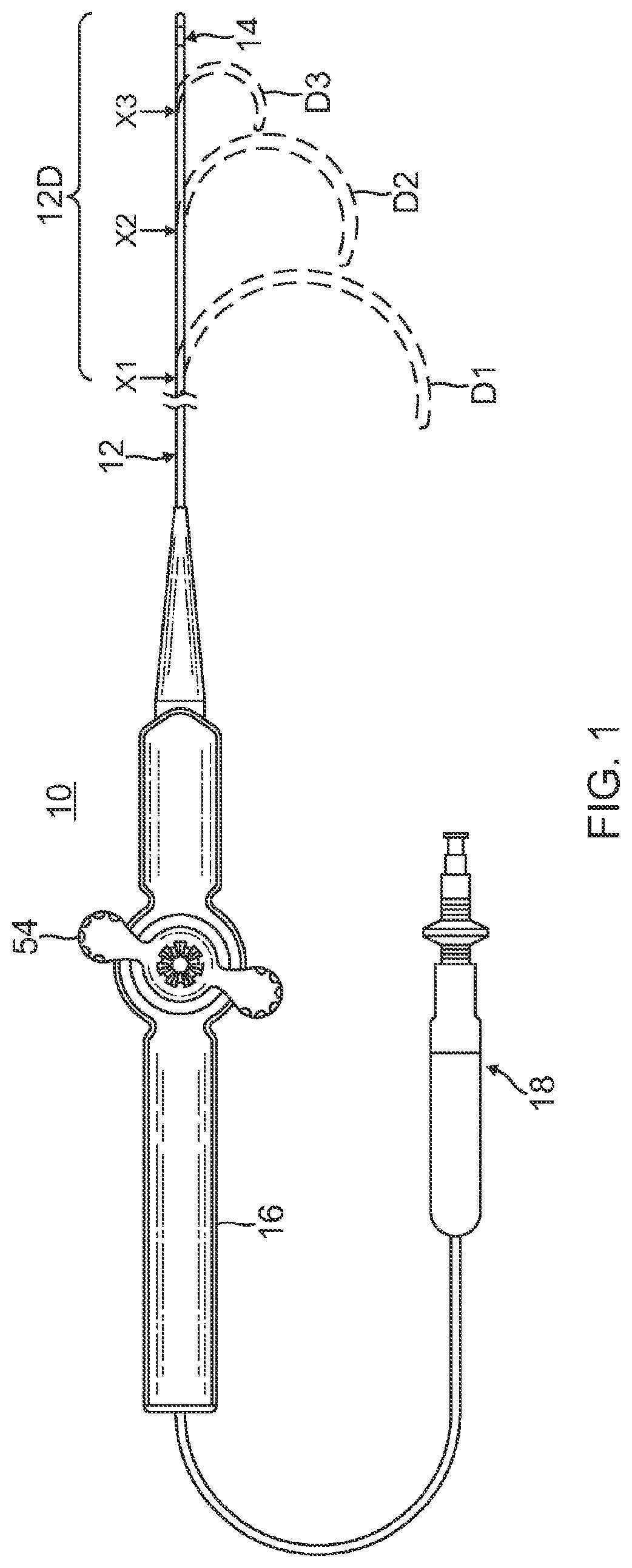
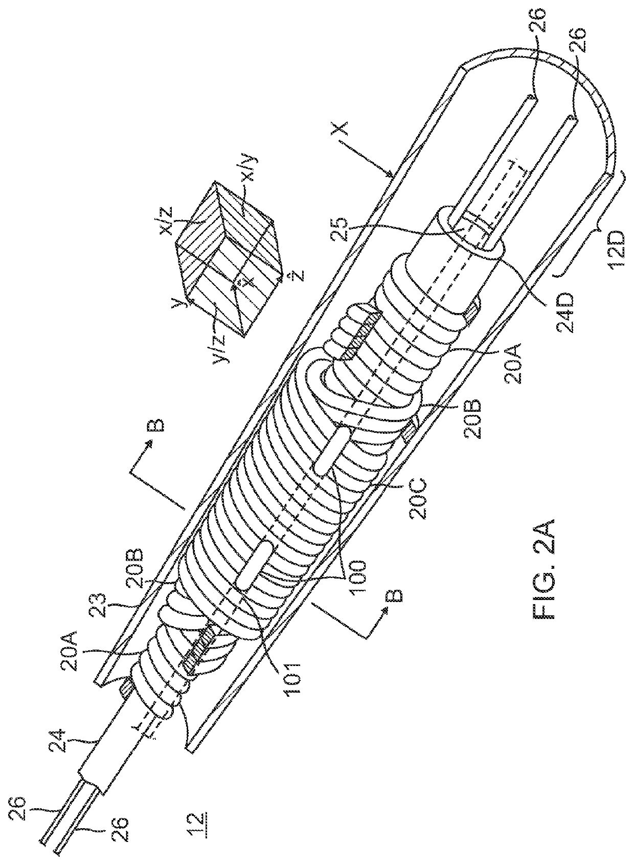
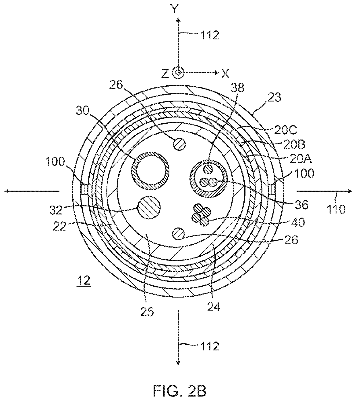
[0118]A shaft assembly, comprising: (a) a proximal section extending distally along a longitudinal axis, the proximal section including a proximal shaft defining a proximal lumen; (b) a distal section extending distally from the proximal section including a distal shaft defining a distal lumen configured to align with the proximal lumen, the distal section being configured to be biased to deflect laterally away from the longitudinal axis into a deflection curvature having a width, the distal section being configure to fit within a cardiovascular anatomical passageway; and (c) at least one stiffener member configured to selectively translate along the longitudinal axis, the at least one stiffener member being configured to counteract the lateral bias of the distal section and thereby reduce the width of the deflection curvature based on a longitudinal position of the stiffener member relative to the distal section.

example 2

[0119]The shaft assembly of Example 1, the at least one stiffener member being disposed within the proximal lumen and being selectively translatable through the distal lumen.

example 3

[0120]The shaft assembly of any one or more of Examples 1 through 2, the deflection curvature width ranging from approximately 0 mm to approximately 55 mm.


PUM


Abstract

A guiding sheath assembly has a shaft that is operable to define more than one deflection curvature and defines a lumen to slidably receive a cardiovascular catheter. The guiding sheath assembly includes a proximal section, a distal section, and a stiffener member. The proximal section has a proximal shaft that defines a proximal lumen extending distally along a longitudinal axis to the distal section. The distal section has a distal shaft that defines a distal lumen that is configured to be biased (e.g., resiliently biased) laterally away from the longitudinal axis. The stiffener member is a rigid elongate member, such as an inner tubular member, that is configured to counteract the bias of the distal shaft. Longitudinal movement of the stiffener member relative to the distal section enables the operator to select and set a deflection curvature of the distal section.

Description

PRIORITY[0001]This application is a continuation-in-part of U.S. patent application Ser. No. 14 / 715,013, entitled “Catheter with Adjustable Deflection,” filed May 18, 2015, published as U.S. Pub. No. 2016 / 0339207 on Nov. 24, 2016, the disclosure of which is incorporated by reference herein.FIELD OF INVENTION[0002]This invention relates to electrophysiologic (EP) catheters, in particular, deflectable guide sheaths for use with EP catheters for mapping and / or ablation in the heart.BACKGROUND[0003]Electrode catheters have been in common use in medical practice for many years. They are used to stimulate and map electrical activity in the heart and to ablate sites of aberrant electrical activity.[0004]In use, the electrode catheter is inserted into a major vein or artery, e.g., femoral vein, and then guided into the chamber of the heart which is of concern. Within the heart, the ability to control the exact position and orientation of the catheter tip is critical and largely determines h...

Claims


Application Information

Patent Timeline
IPC IPC(8): A61M25/01
CPCA61M25/0102A61M2025/0177A61M2025/0161A61M25/0138A61M25/0147A61M2025/09083A61M25/0136A61M25/0113A61B2018/00577A61B2018/00351A61B18/1492A61B2218/002A61B2090/065
Inventor TANG, RAYMOND Y.STANLEY, MARK T.BEECKLER, CHRISTOPHER T.
Owner BIOSENSE WEBSTER (ISRAEL) LTD
Learn More