Dust Shield Device

Active Publication Date: 2020-07-16
COONER CHARLES C
View PDF0 Cites 3 Cited by
  • Summary
  • Abstract
  • Description
  • Claims
  • Application Information

AI Technical Summary

Problems solved by technology

The suction ports and vents also draw in airborne dust above the device.
Second, the device uniformly draws in airborne dust above and around the circumference of the mixing pai

Method used


Image

  • Dust Shield Device
  • Dust Shield Device
  • Dust Shield Device

Examples


Embodiment Construction

[0024]While this invention is susceptible to embodiment in many different forms, the drawings show and the specification describes in detail a preferred embodiment of the invention. It should be understood that the drawings and specification are to be considered an exemplification of the principles of the invention. They are not intended to limit the broad aspects of the invention to the embodiment illustrated.

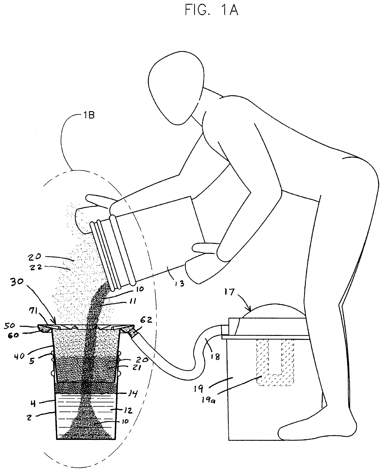
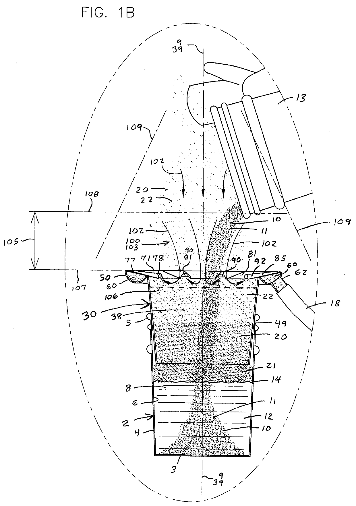
[0025]The present invention pertains to a dust reduction and splash guard device placed on a conventional mixing pail 2 to facilitate the pouring and mixing of a powdery material 10 and water 12 inside the pail to form a construction material, such as plaster, grout, cement or dry wall joint compound. The cylindrical mixing container or pail 2 has a flat bottom 3, tubular sidewall 4, circular top rim 5, smooth inside surface 6, open interior 8 and central axis 9. The sidewall 4 is cylindrical and generally normal to the bottom 3, but can be slightly tapered and narrower at the...


PUM


Abstract

The present invention is a dust shield device that secures over a mixing pail. Powdery material, such as plaster, cement, grout or the like, is poured through the device, and mixed with water inside the pail. The device includes a mounting sleeve, a radial manifold housing and a funnel shaped lid. The manifold housing and lid form a radial pneumatic channel with a circumferentially disbursed air intake that generates a radially uniform airflow that draws in airborne dust that would otherwise escape to the surrounding air. The manifold is connected to a vacuum with an air filter, and generates a dust shield zone air intake zone above the device. The manifold lid forms a radial guard to prevent downward flows of material and water from entering the manifold, and forms a splash guard to retain upwardly projected splashes of material and water inside the pail.

Description

TECHNICAL FIELD OF THE INVENTION[0001]This invention relates to a dust shield device that fits over a mixing pail, allows a powdery material and water to pour through its open interior and into the pail, forms a radial manifold with a circumferentially disbursed air intake that generates a substantially uniform airflow to draw in airborne dust that would otherwise escape to the surrounding air, allows dust below the air intake to settle onto the surface of the mixture inside the pail, forms a radial baffle to retain splashes of material and water during mixing, and increases the effective diameter of the pail to funnel material, water and splashes into the pail.BACKGROUND OF THE INVENTION[0002]A variety of building construction materials are sold in powder or granular form for mixing with water prior to use. Plaster, grout, cement and drywall joint compound are examples of these products. Once mixed, the material is quickly applied before it begins to cure. The products are mixed at...

Claims


Application Information

Patent Timeline
IPC IPC(8): B01F15/00
CPCB01F2215/0047B01F15/00993B01F13/002B01F15/00967B08B15/00B01F27/13B01F33/50115B01F35/184B01F35/186B01F35/189B01F33/5011B01F2101/28
Inventor COONER, CHARLES C.
Owner COONER CHARLES C
Why Eureka
Try Eureka