Method for Producing a Micromechanical Element

a micromechanical element and micro-mechanical technology, applied in the direction of fluid speed measurement, instrumentation, and mechanical device details, can solve the problems of material removal in the functional layer, and achieve the effects of increasing the stability of the micromechanical structure, reducing the size of the cavity, and reliably removing the closure cap material

Active Publication Date: 2019-03-28
ROBERT BOSCH GMBH
View PDF5 Cites 0 Cited by
  • Summary
  • Abstract
  • Description
  • Claims
  • Application Information

AI Technical Summary

Benefits of technology

[0015]One of the advantages achieved thereby is that, by way of example, an etching access is constricted by means of or with the aid of the gridlike structure and faster closure is thus made possible. By means of the grid structure, smaller interspaces are produced, which can be closed more simply, more cheaply and more rapidly. A shorter duration of the closure process enables the closure material of the closure layer to be deposited predominantly on the surface and not on the microelectromechanical sensor element in the cavity. Furthermore, a long process duration during the deposition of the closure material, if etching components, for example critical gases, are used, leads to a material removal in the functional layer.
[0016]The closure process is likewise facilitated since it is possible to use even closure materials which grow greatly in a vertical direction and only little in a lateral direction, in particular in the case of large openings. The flexibility in the choice of a closure material is thus increased. Further advantages are, for example, that by virtue of the grid structure the closure material to be applied on said grid structure contaminates the cavity to a lesser extent, or not at all, since the closure process can be carried out more rapidly and in a shorter time. Furthermore, it is possible to use a greater selection of closure materials, that is to say utilize in particular processes for closing the cavity which are carried out with expedient process or auxiliary gases, which in particular do not adversely affect the functional layer in the cavity, or adversely affect it to a lesser extent. The process reliability is likewise increased by virtue of the grid structure since the width or the diameter to be closed is reduced by virtue of the grid structure, or larger overall openings can be closed. A further advantage is that the gridlike structure enables a lower process pressure during the closure process, which enables a lower internal pressure in the cavity. This improves the quality of the micromechanical structure, and thus leads to a reduced power consumption in conjunction with better performance of the micromechanical sensor.
[0018]In accordance with one advantageous development, removing the sacrificial layer is carried out by means of a vapor phase etching process. An advantage of this is that the sacrificial layer can be removed in a simple manner
[0020]In accordance with a further advantageous development, at least part of the material of the closure cap below the grid structure and corresponding to the latter is retained. In other words, a supporting structure is thereby formed below the grid or the grid structure, which overall increases the stability of the micromechanical structure.
[0023]In accordance with a further advantageous development, corresponding to the grid structure, below the grid structure closure cap material is at least partly arranged in the cavity. An advantage of this is that a supporting structure for the grid structure is thereby formed, which improves the stability overall.

Problems solved by technology

Furthermore, a long process duration during the deposition of the closure material, if etching components, for example critical gases, are used, leads to a material removal in the functional layer.

Method used


Image

  • Method for Producing a Micromechanical Element
  • Method for Producing a Micromechanical Element
  • Method for Producing a Micromechanical Element

Examples


Embodiment Construction

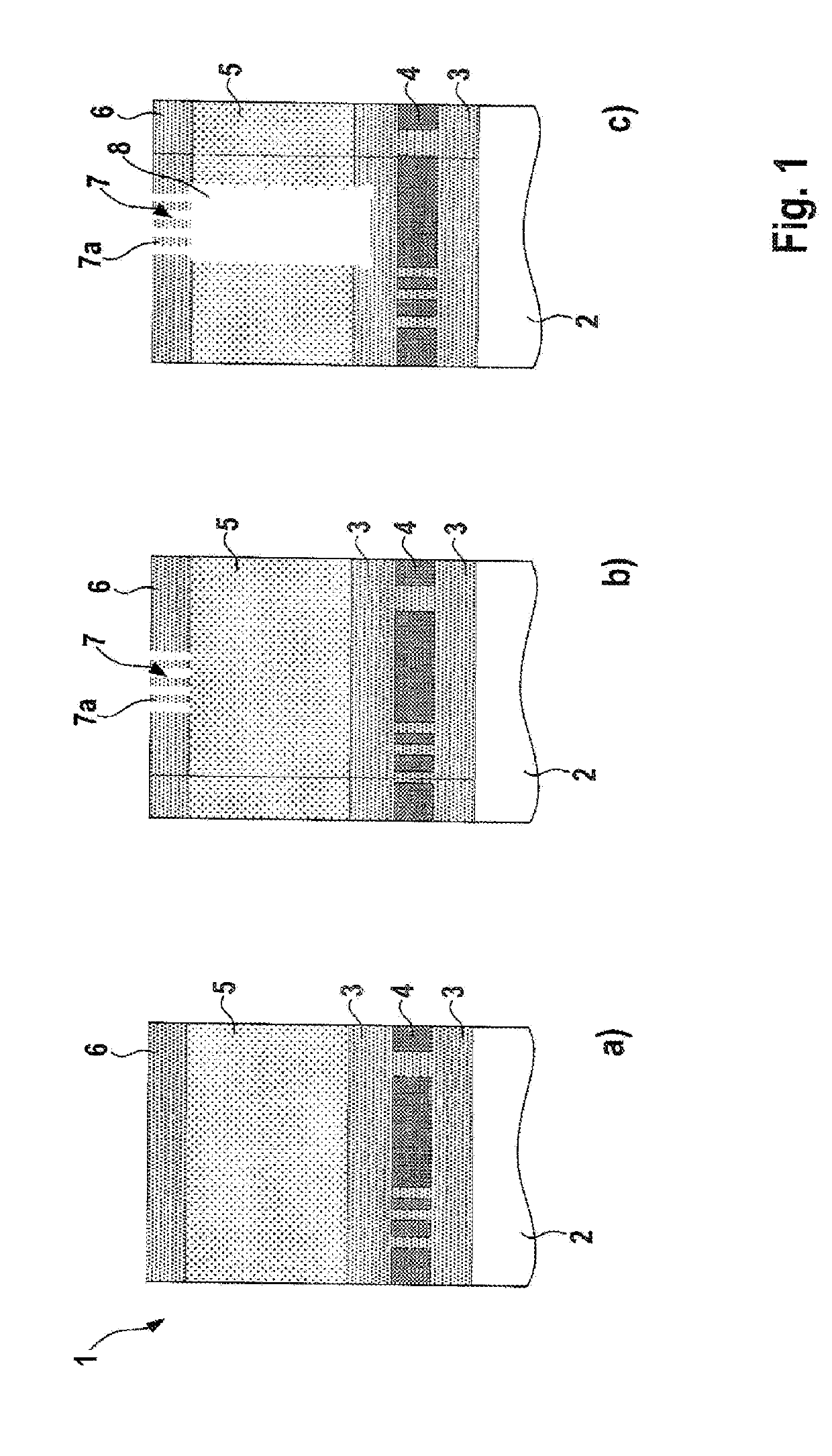
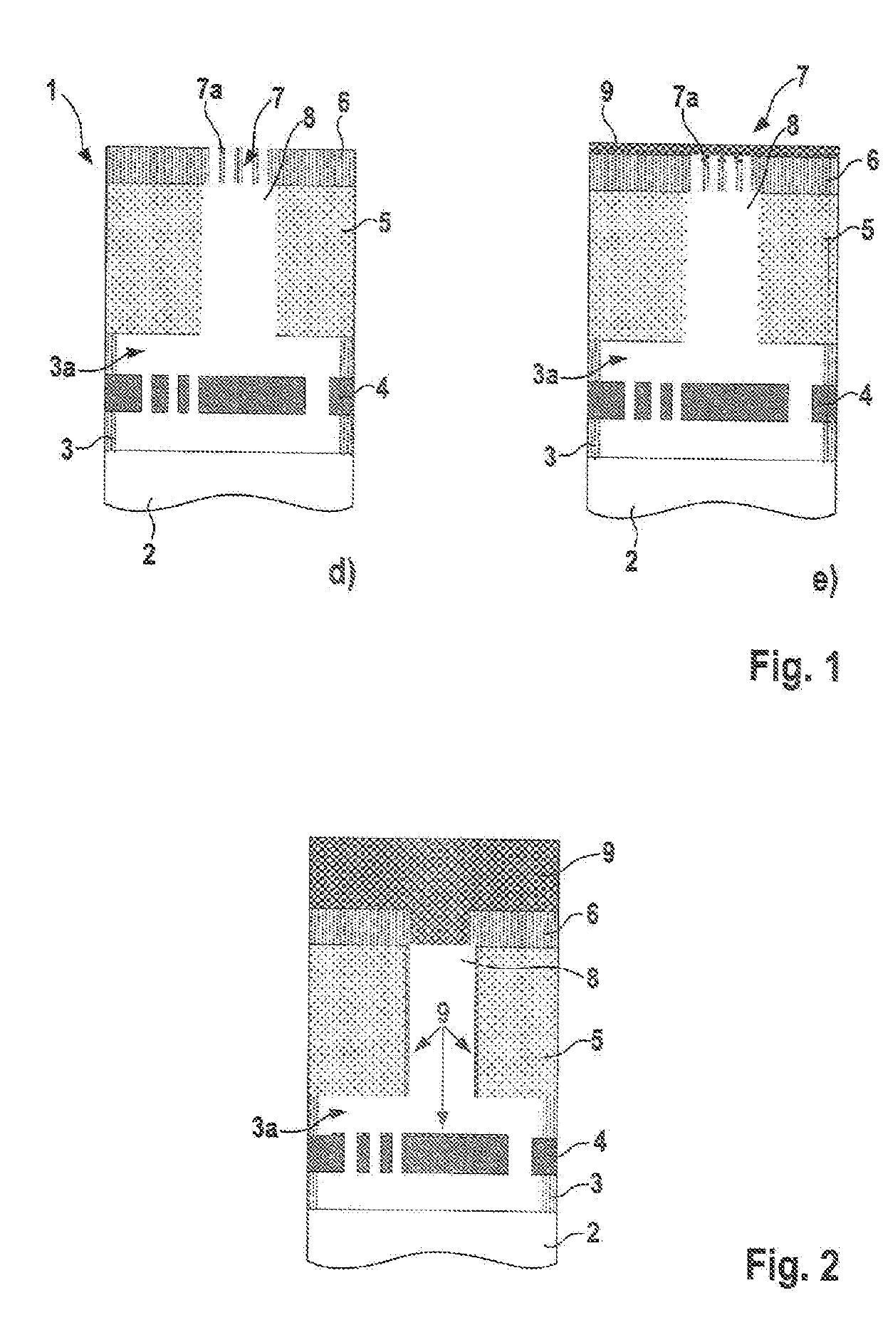
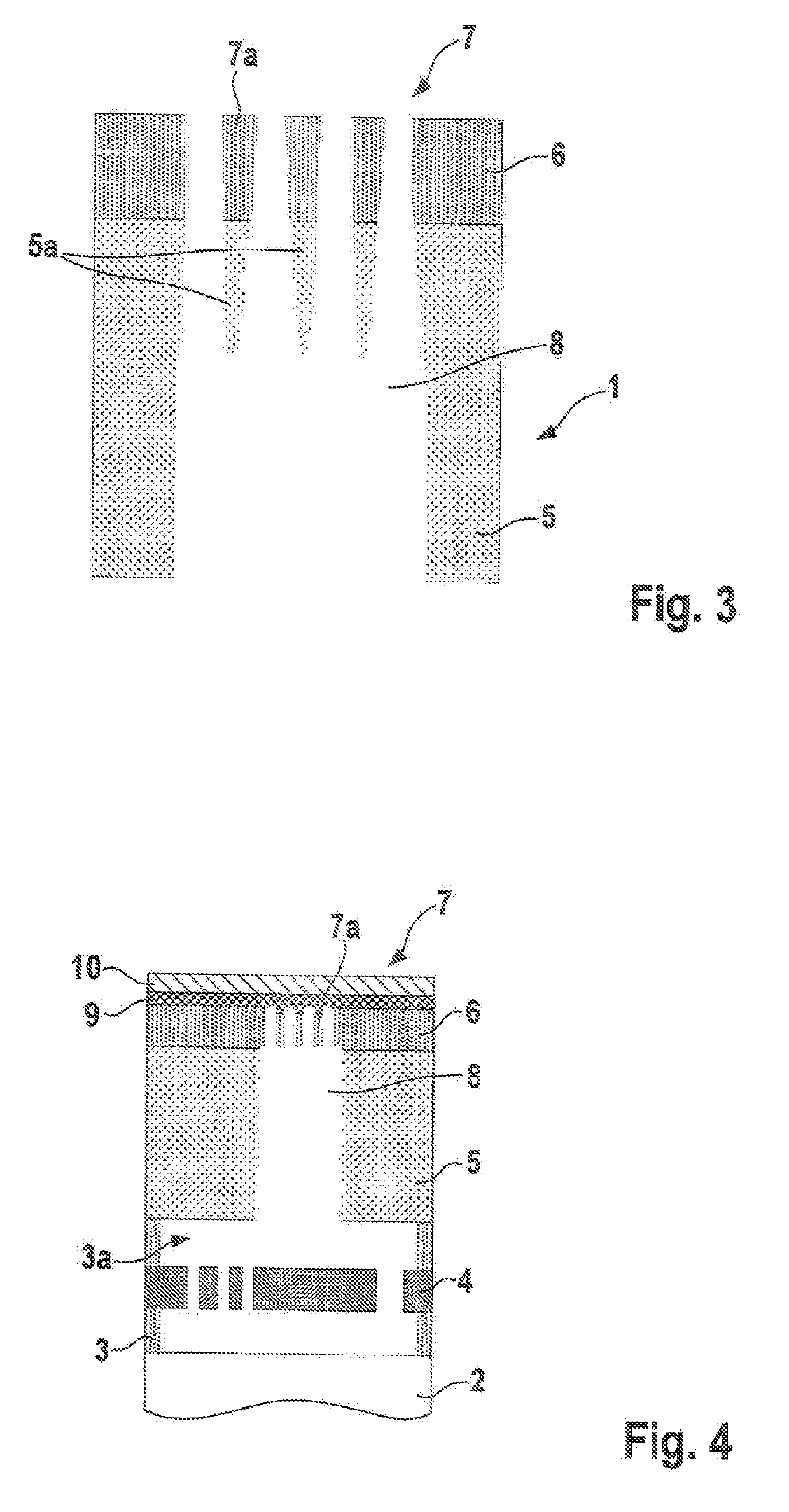
[0034]FIGS. 1a-e show steps of a method in accordance with one embodiment of the present disclosure.

[0035]In detail, FIG. 1a shows a micromechanical structure 1 comprising a plurality of layers one above another. The bottommost layer 2 is formed by a substrate. A sacrificial layer 3, for example produced from silicon oxide, is arranged on said substrate layer 2, a functional layer 4 for a microelectromechanical sensor being embedded into said sacrificial layer. A closure cap layer 5, for example in the form of a cap, is arranged above the sacrificial layer 3. Grid material 6 has in turn been applied or deposited on said closure cap layer 5.

[0036]In order to produce the micromechanical layer structure 1, for example the functional layer 4 is produced on the sacrificial layer 3 and then material of the sacrificial layer 3 is once again applied on the functional layer 4 until the part of the functional layer 4 which forms the micromechanical sensor is completely enclosed by the sacrifi...


PUM

PropertyMeasurementUnit
micromechanical structureaaaaaaaaaa
internal pressureaaaaaaaaaa
electricalaaaaaaaaaa

Abstract

A method for producing a micromechanical element includes producing a micromechanical structure, the micromechanical structure having: a functional layer for a micromechanical element, a sacrifical layer at least partly surrounding the functional layer, and a closure cap on the sacrifical layer. The method further includes applying a cover layer on the micromechanical structure. The method further includes producing a grid structure in the cover layer. The method further includes producing a cavity below the grid structure, as access to the sacrifical layer. The method further includes at least partly removing the sacrifical layer. The method further includes applying a closure layer at least on the grid structure of the cover layer for the purpose of closing the access to the cavity.

Description

[0001]This application claims priority under 35 U.S.C. § 119 to patent application number DE 10 2017 216 941.9, filed on Sep. 25, 2017 in Germany, the disclosure of which is incorporated herein by reference in its entirety.BACKGROUND[0002]The disclosure relates to a method for producing a micromechanical element.[0003]The disclosure furthermore relates to a micromechanical structure.[0004]Although the present disclosure is applicable to any micromechanical structures, the present disclosure is described with respect to micromechanical resonator structures.[0005]Many micromechanical sensors and actuators use a defined internal pressure in a hollow space in which movable elements of the micromechanical sensor are situated, for example an oscillating structure of a micromechanical resonator. In the case of a micromechanical resonator, usually a movable structure is placed on silicon oxide or a similar material as sacrificial layer and is at least partly surrounded thereby. After a clos...

Claims


Application Information

Patent Timeline
Patent Type & Authority Applications(United States)
IPC IPC(8): B81C1/00G01D5/06B81B7/00
CPCB81C1/00293G01D5/06B81B7/0041B81C2201/0132B81C2203/0136B81B7/0006B81C1/00095H01L21/76898H01L23/5283B81B2207/07B81C1/00333B81C2203/0145
Inventor KUHNKE, MARKUSSTAHL, HEIKOMAJONI, STEFAN
Owner ROBERT BOSCH GMBH
Why Eureka
Try Eureka