Mould plate

Active Publication Date: 2022-07-12
KME SPECIAL PROD GMBH & CO KG
View PDF11 Cites 0 Cited by
  • Summary
  • Abstract
  • Description
  • Claims
  • Application Information

AI Technical Summary

Problems solved by technology

The heat load on copper moulds in continuous strand casting may lead to considerable material stresses within the copper alloy, in particular in thin slab continuous casting plants.
The casting side tries to expand, but at the same time this expansion is hindered by the rear side facing the cooling water.
This leads to high internal material stresses.
If the internal material stresses exceed the elasticity limit of the copper alloy, this leads to a plastic deformation of the casting side, known as bulging.
As well as material fatigue, the plastic deformation causes a gap to form between the wide sides and narrow sides of a mould.
This may lead to damage to the mould plates during width adjustment.
The reduced wall thicknesses resulting from remachining shorten the remaining service life of the mould.
This in turn leads to shorter maintenance interva

Method used


Image

  • Mould plate
  • Mould plate

Examples


Example

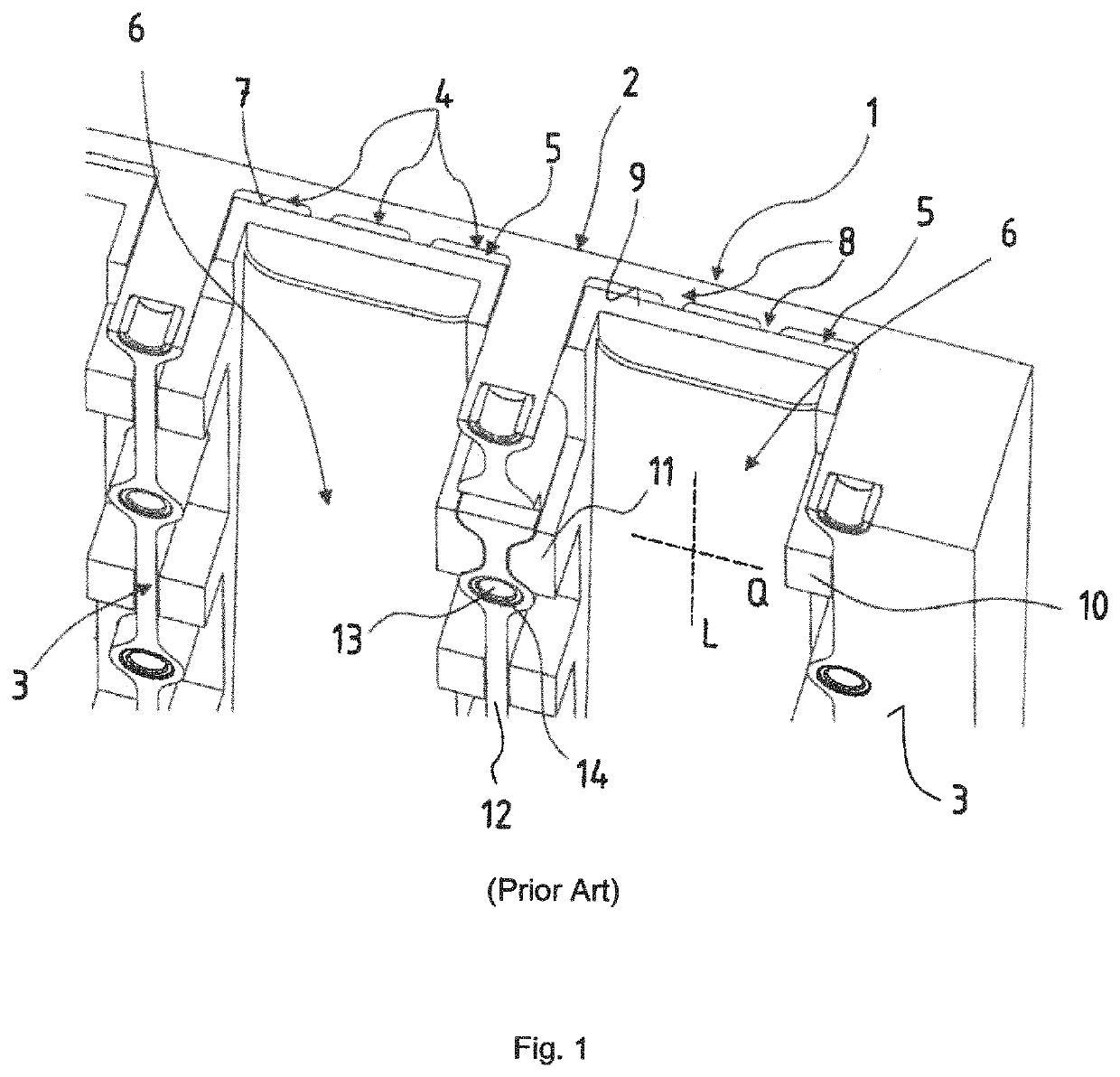
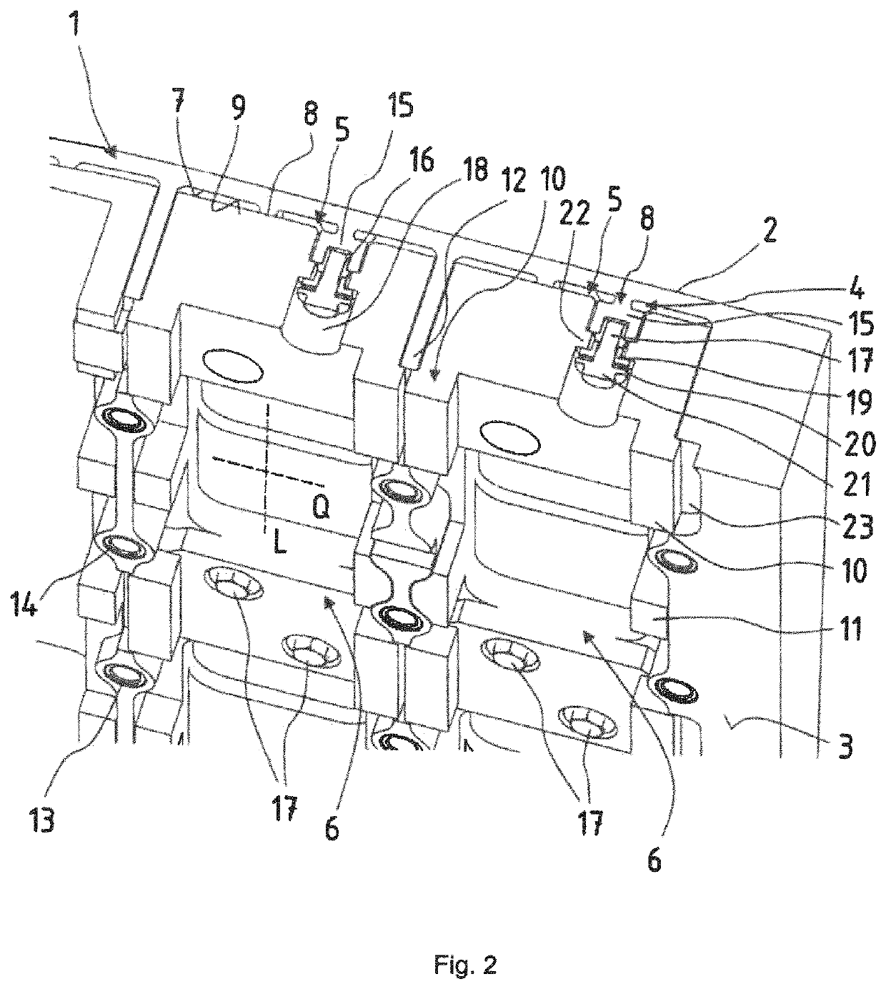
[0033]FIG. 1 shows the prior art and serves to explain the technological background. It is not an embodiment for which protection is claimed. The invention is then explained in more detail with reference to an exemplary embodiment shown purely schematically in FIG. 2.

[0034]FIG. 1 shows in a perspective view a partial region of a mould plate 1 in partial cross-section. The reference signs used to explain the mould plate 1 in FIG. 1 are also used for components of substantially the same function in the mould plate 1 according to the invention as shown in FIG. 2.

[0035]The mould plate 1 in FIG. 1 has a casting side facing away from the viewer, and a rear side 2 facing the viewer. In the installation position, the rear side 2 rests on a support plate (not shown in detail). During casting operation, hot melt on the casting side 2 is cooled in that heat is extracted from the mould plate 1 and dissipated via cooling water conducted through cooling gaps 4, which in turn are situated inside c...


PUM

PropertyMeasurementUnit
Thicknessaaaaaaaaaa
Lengthaaaaaaaaaa

Abstract

A mould plate includes a casting side and a rear side facing away from the casting side and having a cooling channel configured to open towards the rear side and having a cooling face opposite the casting side. An insert is arranged in the cooling channel to form a cooling gap between an inner face of the insert and the cooling face. A fastening bolt connects the insert to a fastening point in the cooling face, wherein the cooling gap extends, viewed from the fastening point towards the casting side, to an area below the fastening point.

Description

CROSS-REFERENCES TO RELATED APPLICATIONS[0001]This application is the U.S. National Stage of International Application No. PCT / DE2020 / 100005, filed Jan. 8, 2020, which designated the United States and has been published as International Publication No, WO 2020 / 156607 A1 and which claims the priority of German Patent Application, Serial No, 10 2019 102 313.0, filed Jan. 30, 2019, pursuant to 35 U.S.C. 119(a)-(d).BACKGROUND OF THE INVENTION[0002]The invention concerns a mould plate.[0003]The heat load on copper moulds in continuous strand casting may lead to considerable material stresses within the copper alloy, in particular in thin slab continuous casting plants. Mould plates are subjected to extreme heat loads on their hot side facing the melt, i.e. the casting side, while the rear side facing the cooling water remains largely cold. Within the mould plate, which is a few millimeters thick, a temperature gradient of several 100 degrees Kelvin occurs between the hot side and the wat...

Claims


Application Information

Patent Timeline
IPC IPC(8): B22D11/055
CPCB22D11/055B22D11/112B22D11/124
Inventor HUGENSCHÜTT, GERHARDROLF, THOMAS
Owner KME SPECIAL PROD GMBH & CO KG
Why Eureka
Try Eureka