Split Nut Valve Seat Puller

Active Publication Date: 2020-07-16
COLBURN WILLIAM +2
View PDF0 Cites 0 Cited by
  • Summary
  • Abstract
  • Description
  • Claims
  • Application Information

AI Technical Summary

Benefits of technology

[0006]The split nut segments are placed in a suitable base in a manner which allows all of the split nut segments to move and to be moved inwardly (toward the center longitudinal axis of the invention) so as to allow the v-grooves of the split nut segments to engage the v-grooves of the seat puller stem. Once the v-grooves of the plurality of split nut segments are engaged against the v-grooves of the seat puller stem and with the duckbill in place against the valve seat, the pancake jack is used to raise the invention and the seat puller stem, which pulls the valve seat from the fluid end.
[0007]The invention has a top covering the base in which the split nut segments are placed. The base has a conical interior surface designed to allow the split nut segments and the v-grooves thereon to slide downward and inward to engage the v-grooves of the seat puller stem. The conical interior surface of the base improves functionality by using gravity to aid this motion. The split nut segments resist sliding down to the bottom of the conical interior by the use of helical springs placed in holes between each of the split nut segments to separate each split nut segment. A wave spring placed atop the base between the base and the top of the invention raises the top off the base and creates sufficient space in the interior of the invention when not in use to allo

Problems solved by technology

It is commonly known in oil field work that fluid ends and the parts which comprise them are subjected to high levels of wear.
Valve seats, for example, require frequent replacement because of the amount of wear to which they are subjected.
Generally, valve seats are difficult to remove and replace.
The

Method used


Image

  • Split Nut Valve Seat Puller
  • Split Nut Valve Seat Puller
  • Split Nut Valve Seat Puller

Examples


Example

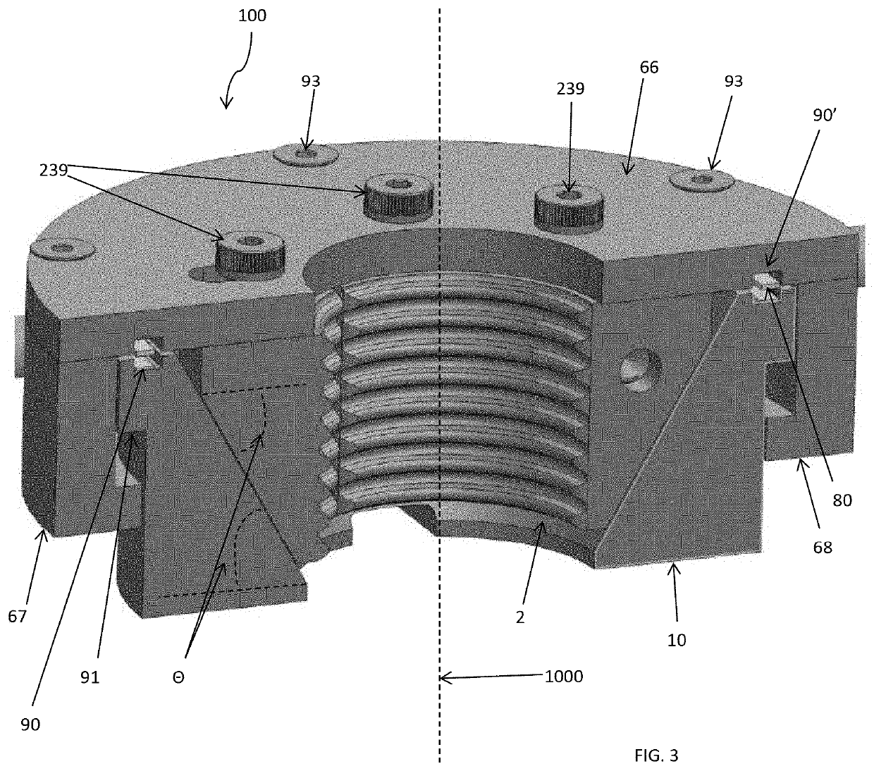
[0022]To aid understanding of the invention, the following conventions are provided. The invention consists of two primary inventive pieces which operate jointly—the assembled split nut segments, springs, base and top as one inventive part and the v-grooves of the seat puller stem as the other. Further, the assembled split nut segments, springs, base and top, depicted in cutaway view in FIG. 3 are generally in the form of a hollow ring having a diameter, height and (imaginary) longitudinal axis 1000.

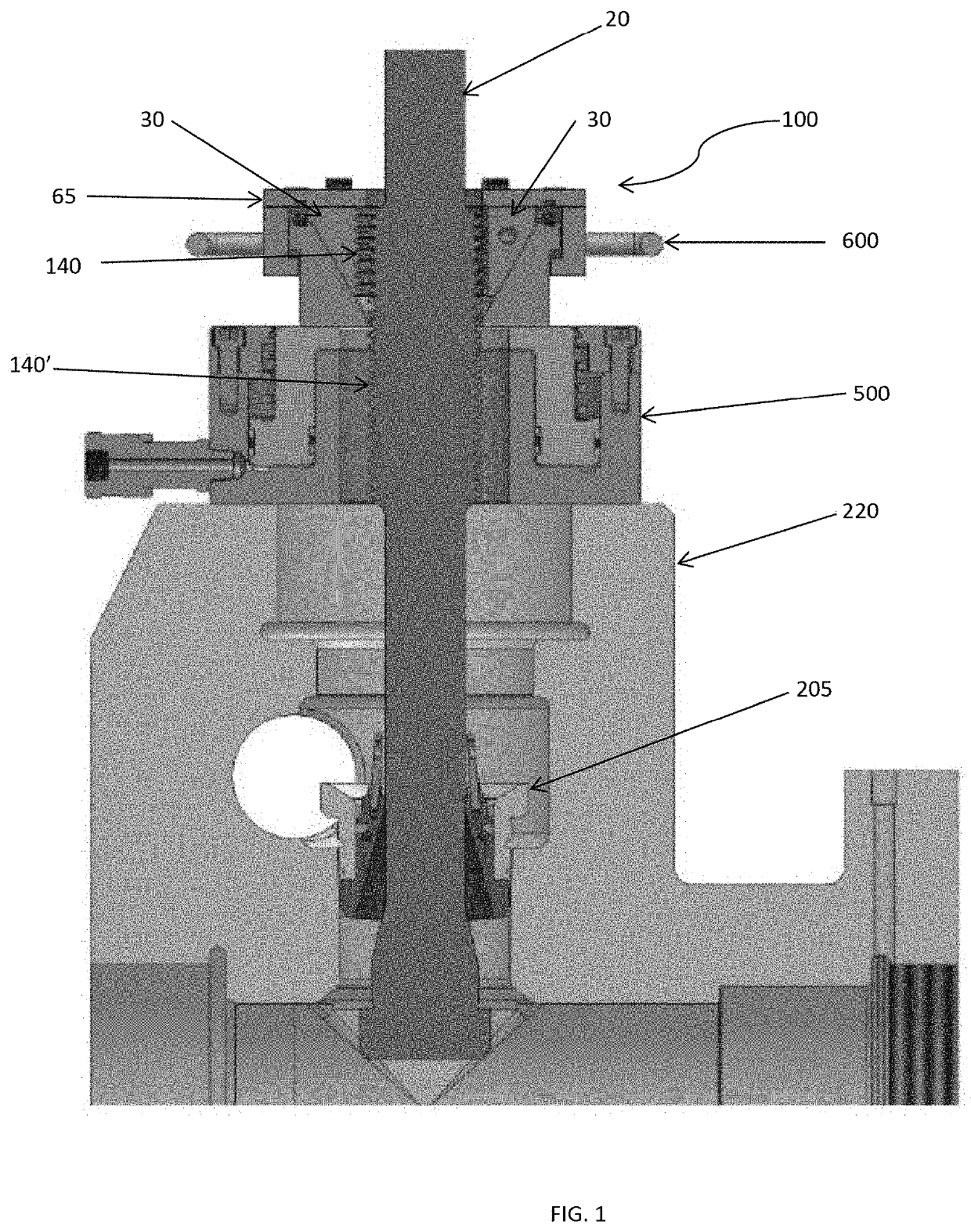
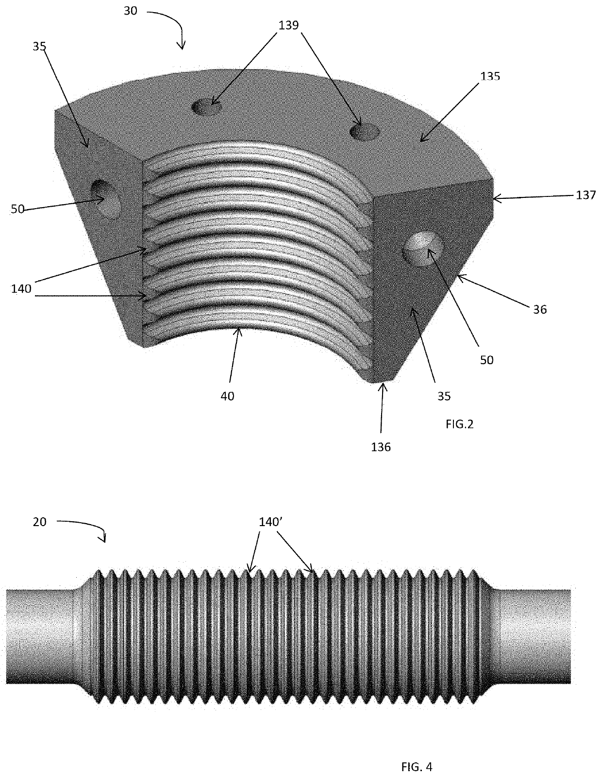
[0023]As depicted in FIG. 1, the invention 100 uses a plurality of split nut segments 30 to engage a seat puller stem 20. As depicted in FIG. 2, each split nut segment 30 is generally in the form of an arcuate solid made by cutting a solid circular ring into multiple equal pieces. In this sense, the set of split nut segments 30 are comparable to a split nut known in the industry, such as one sold by AllFasteners. https: / / www.allfasteners.com / tower-products / tower-nuts / split-nut. The descr...


PUM


Abstract

The invention is an improved tool for pulling a valve seat from a valve in a fluid end. The invention replaces the standard threaded nut and stem commonly used in such tools with a split nut comprising a plurality of removeably engageable split nut segments placed within a base and a stem configured to be used with the plurality of removeably engageable split nut segments. In the preferred embodiment, each split nut segment possesses a center-facing surface relative to the longitudinal axis of the invention comprising a set of horizontal v-grooves suitable to be disposed against complementary v-grooves of the stem. The base permits the plurality of split nut segments to be placed in an engaged position permitting the v-grooves of the split nut segments to removeably engage the v-grooves of the stem securely or to be placed in a disengaged position. The base containing the split nut segments is durable enough to be used in oil field work but lightweight enough to be used by individual or groups of workers safely.

Description

BACKGROUND OF THE INVENTIONBrief Description of Prior Art[0001]It is commonly known in oil field work that fluid ends and the parts which comprise them are subjected to high levels of wear. Valve seats, for example, require frequent replacement because of the amount of wear to which they are subjected. Generally, valve seats are difficult to remove and replace. They require specialized tools and a considerable amount of labor. One tool commonly used to pull valve seats is a stem, onto which is fitted a duck bill and which is inserted into a valve of a fluid end. A stem nut is then screwed by hand onto the valve seat stem. This takes time. The tool is heavy, and the number of steps to place the tool into position and use it creates multiple opportunities for mistakes and worker injuries. In the common form of the tool, the tool must be raised over the heads of workers in order to be placed into position. Given the size and weight of the tool, this exposes workers to a risk of serious...

Claims


Application Information

Patent Timeline
IPC IPC(8): B25B27/26F16K51/00E21B34/02
CPCE21B34/02F16K51/00B25B27/26F16K1/42B25B27/064
Inventor COLBURN, WILLIAMBETANCOURT, RICARDOASH, JR., ROBERT H.
Owner COLBURN WILLIAM
Why Eureka
Try Eureka