
Fire-extinguishing device (variants), lock and release device for fire-extinguishing device (variants), forced activation device for lock and release device, fire-extinguishing system and fire-extinguishing method

Active Publication Date: 2020-07-23
SOVA NIKOLAY VADIMOVICH
View PDF0 Cites 0 Cited by
  • Summary
  • Abstract
  • Description
  • Claims
  • Application Information

AI Technical Summary

Benefits of technology

The invention is a fire-extinction device that solves the problems of previous prototypes by improving reliability and performance. The device has been designed to have better processability, which means it is easier to manufacture and use. As a result, the device's ability to enhance fire extinction has been improved.

Problems solved by technology

Thereby, this results in lock destruction and release of push-bar spring.
Disadvantages of the specified solution are that in the lock and release device, the push-bar sleeve is connected with the spray element through only one slot.
This results in the fact that in the moment of movement the push bar may be positioned noncoaxially towards the axis of exhaust opening, which in its turn will result in its jamming or in breaking-off the closure under angle, by the push bar.
Respectively, this may result both in total failure of the device and in its wrong actuation, which will reduce efficiency of fire extinction.
This, respectively, in case of device actuation, results in ineffective release of GFEA.
Other disadvantages of the specified device include the fact that the lock and release device is connected with the cylinder directly; whereas, the closure element (membrane) is positioned immediately in the lock and release device.
This, respectively, reduces processability of the device and does not allow assembling in the place of installation.
Finally, in case of the device with a forced-actuation device in its assembly, among disadvantages there are the following: that the actuation device is supposed to be mounted in the upper part of spray-element cap, which, respectively, also decreases processability of the device in general, because in this case, an additional working hole is required.
Performance of such forced-actuation device is also questioned, so far as it requires to have a direct current supply in the system.

Method used


Image

  • Fire-extinguishing device (variants), lock and release device for fire-extinguishing device (variants), forced activation device for lock and release device, fire-extinguishing system and fire-extinguishing method

Examples


Embodiment Construction

[0013]Further, find variants of realization of this invention which reveal examples of its realization in certain variants of performance. Nevertheless, the description itself is not intended to limit the scope of rights conferred by this patent. Rather, one should be based on the fact that the claimed invention may as well be realized in other ways in such a manner so to include differing elements and specifications or combinations of elements and specifications, which are the same as the elements and specifications as described herein, in combination with other existing and future technologies.

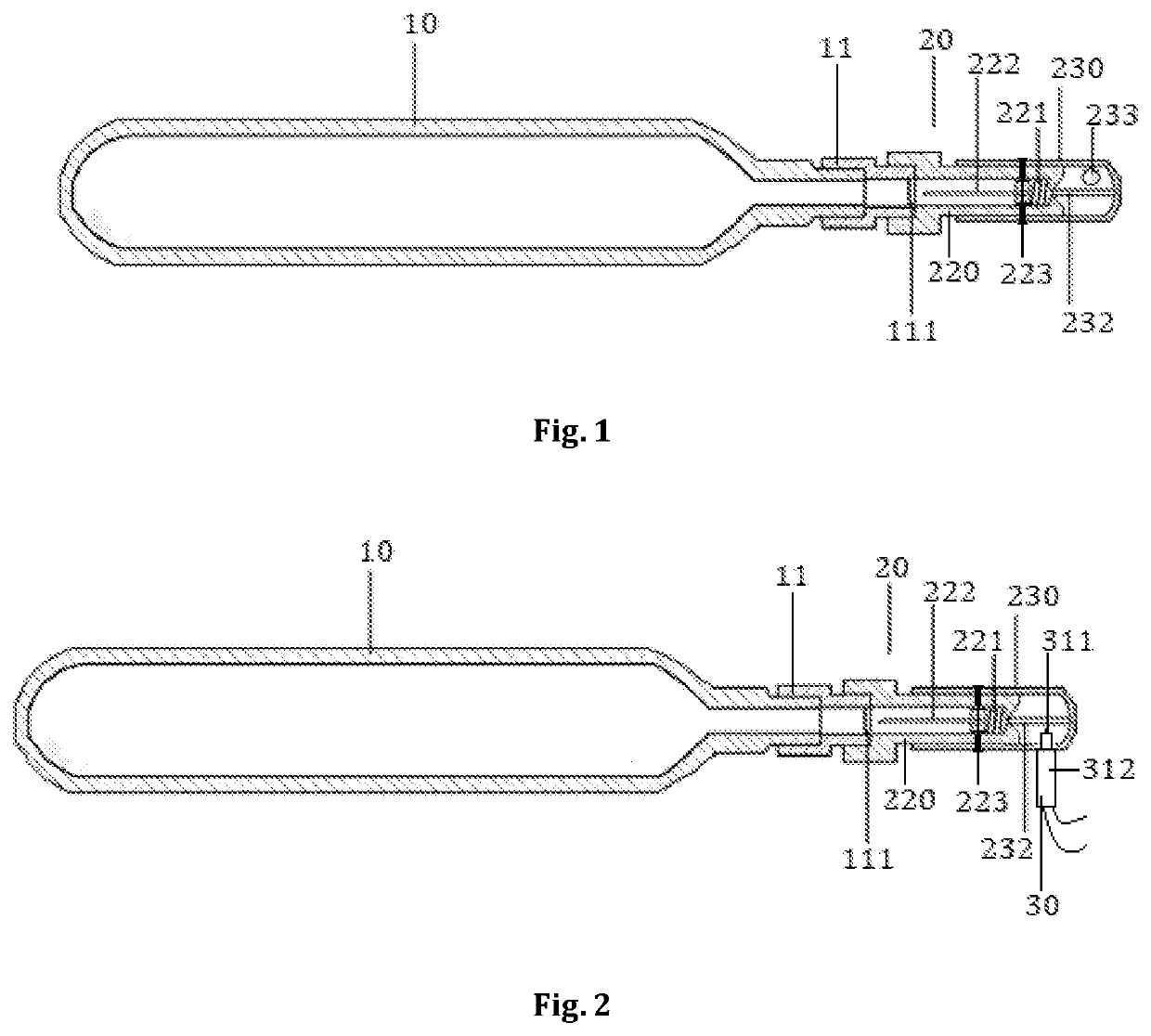
[0014]In the preferable variant of realization there is provided the fire-extinguishing device, which is a container filled-up with gas fire-extinguishing agent, with the locking nut; whereas, the locking nut is connected with the container's outlet and includes a closure element which retains the fire-extinguishing agent inside the container under pressure; and a lock and release device, wh...


PUM


Abstract

The proposed technical solution relates to fire prevention equipment and can be used in industrial and civilian properties, including with an increased risk of fire, for locating hot spots, and also for efficiently extinguishing fires in facilities using automatic fire-extinguishing systems. The technical problem addressed by the claimed invention is to produce a fire-extinguishing device which does not have the drawbacks mentioned and has increased reliability, efficiency and manufacturability. The technical result of the claimed invention consists in elimination of the drawbacks of the prior art, in an increase in the reliability and manufacturability of a fire-extinguishing device and thus in an increase in the fire-extinguishing efficiency overall.

Description

FIELD OF INVENTION[0001]The suggested technical solution is relating to fire-extinguishing equipment and may be used in industrial and civilian facilities, including, in those with increased fire hazard, in order to localize fire sources, as well for effective fire extinguishing in the rooms with deployment of automatic fire-extinguishing systems.BACKGROUND OF INVENTION[0002]There is a known fire-extinguishing device as described in application US2017036048 (A1), published on 9 Feb. 2017 on 15 sheets. The known fire-extinguishing device consists of a cylinder and a lock and release device which includes a thermal lock being destructed once the temperature limit is reached. This activates a spring-loaded push-bar which is performed as a hollow needle; it breaks through cylinder's membrane and releases gas fire extinguishing agent (GFEA) which is discharged under pressure through spray element's openings. In an optional performance, the lock and release device includes an electronic d...

Claims


Application Information

Patent Timeline
IPC IPC(8): A62C37/48A62C37/11
CPCA62C37/48A62C35/023A62C37/11A62C2/00A62C99/0027A62C13/62
Inventor SOVA, NIKOLAY VADIMOVICH
Owner SOVA NIKOLAY VADIMOVICH
Learn More