
Filter device and filter system

Active Publication Date: 2020-07-30
GREENFILTEC PTE LTD
View PDF0 Cites 2 Cited by
  • Summary
  • Abstract
  • Description
  • Claims
  • Application Information

AI Technical Summary

Benefits of technology

The present invention improves filter device and system air tightness and reduces operator injury during manufacturing.

Problems solved by technology

In this case, if a frame of the filter device cannot be tightly combined with the filter disposed therein, the gas that should be filtered leaks from a gap between the filter and the frames, resulting in a bad filtering effect.
What's more, the filter device is usually manufactured in a way of aluminum extrusion, which easily produces a sharp corner at an edge or a sharp edge, increasing a chance of injury to an operator during assembly.

Method used


Image

  • Filter device and filter system
  • Filter device and filter system
  • Filter device and filter system

Examples


Embodiment Construction

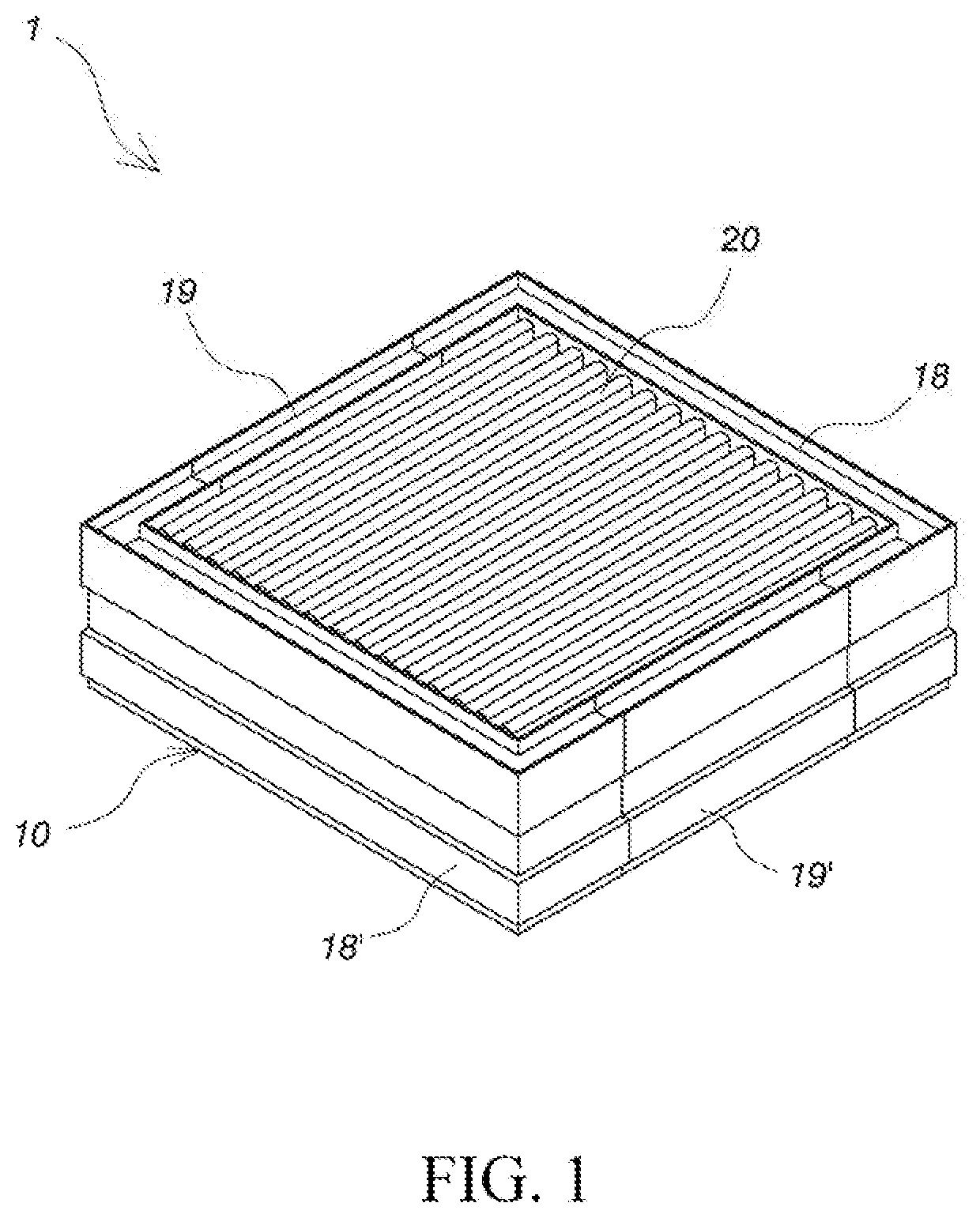
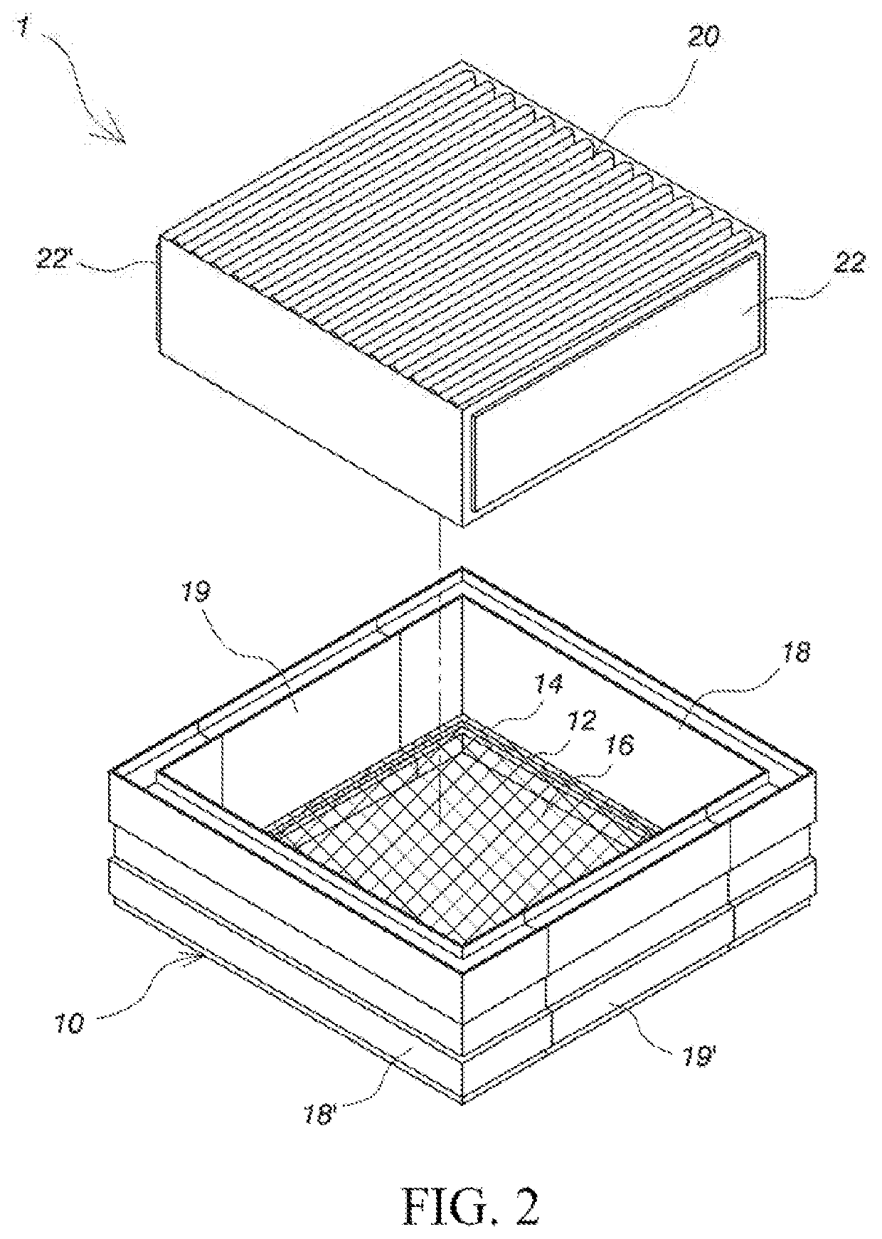
[0048]A filter device of the present invention is disposed in a frame. Further, the filter device and the frame constitute a filter system. In other words, the filter system includes the frame and the filter device.

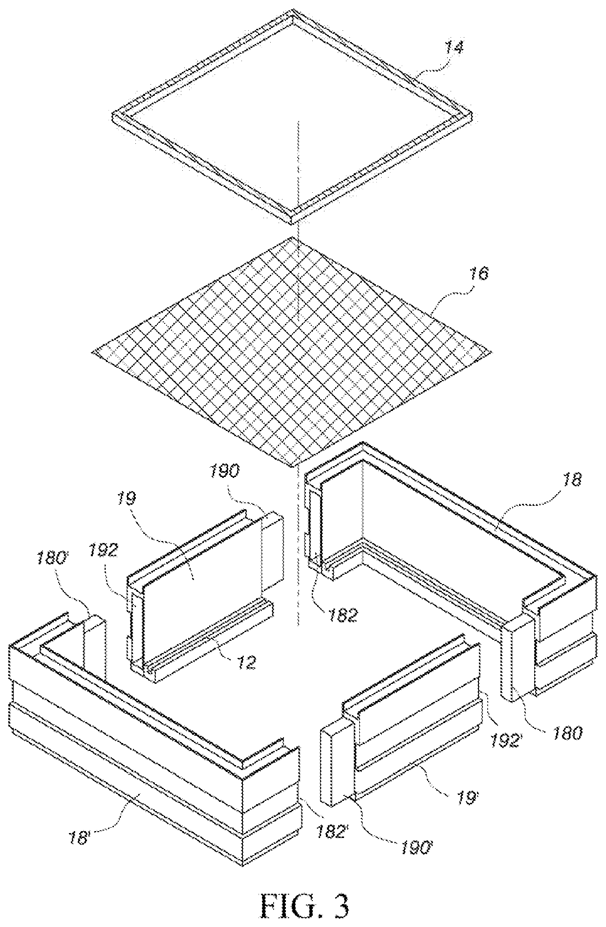
[0049]More specifically, in the embodiment shown in FIG. 1 and FIG. 2, the filter system 1 includes a frame 10 and a filter device 20. In this embodiment, for example, the frame 10 is a rectangular frame. A fixing groove 12 is further disposed in an inner wall and close to a bottom of the frame 10 to fix a filter 16 to the frame 10 using a fixing element 14, such as a rubber fixing strip, embedded into the fixing groove 12. The filter 16 is configured to filter out large particles of a gaseous suspended pollutant, and the filter device 20 may be further disposed in the frame 10. The filter device 20 is configured to filter out a slightly small gaseous suspended pollutant.

[0050]The frame may include at least one engaging frame element and at least one ferromagnetic frame e...


PUM

PropertyMeasurementUnit
Lengthaaaaaaaaaa
Magnetismaaaaaaaaaa
Ferromagnetismaaaaaaaaaa

Abstract

A filter device and a filter system are provided. A magnetic unit is disposed on at least one side of the filter device. The filter device includes a filter and a magnetic fixing device. The filter includes a first side wall. The magnetic fixing device includes a body, a clipping portion, and the magnetic unit. The body includes a top edge, a bottom edge, a first side face, and a second side face opposite to the first side face. The clipping portion includes a top flange extending from the top edge along the facing direction of the first side face by a first distance and a clip plate extending from an outer edge of the top flange toward the bottom edge by a second distance. The first side wall is clipped between the clip plate and the first side face. The magnetic unit is disposed on the second side face. The filter system includes a frame and the filter device.

Description

BACKGROUNDTechnical Field[0001]The present invention relates to a filter device and a filter system; and in particular, to a filter device and a filter system erected at an air inlet of a dust-free room.Related Art[0002]In an industrial manufacturing field such as a semiconductor manufacturing industry, in order to further improve a product yield, a dust-free room is widely used to manufacture a product in a clean, pollution-free, and isolated environment. In order to meet environmental requirements of the dust-free room, a fan and a filter device are generally erected at an air inlet of the dust-free room, so that air flow is driven by the fan to pass through a filter of the filter device and then enters the dust-free room, thereby filtering a gaseous suspended pollutant.[0003]The filter device erected at the air inlet of the dust-free room easily vibrates continuously due to an influence of the air flow of the fan. In this case, if a frame of the filter device cannot be tightly co...

Claims


Application Information

Patent Timeline
IPC IPC(8): B01D46/00H01F7/02B01D46/52
CPCB01D2265/023B01D46/0008B01D2279/51B01D2265/028B01D46/521H01F7/0252B01D46/0006B01D46/0005B01D46/10B01D46/0013B01D46/645B01D46/62Y02A50/2351
Inventor LEE, YU-MINGLIEN, YU-DE
Owner GREENFILTEC PTE LTD
Learn More