Boiler tube reinforcement device and boiler tube reinforcement method

Inactive Publication Date: 2020-07-30
THE CHUGOKU ELECTRIC POWER CO INC
View PDF4 Cites 0 Cited by
  • Summary
  • Abstract
  • Description
  • Claims
  • Application Information

AI Technical Summary

Benefits of technology

[0007]According to one or more embodiments, it becomes possible to reinforce a boiler tube so as to minimize thermal stress (bending force, e

Problems solved by technology

When the boiler for power generation continues to be used over a long period of time, creep-fatigue damage is created in the boiler tubes due to the the

Method used


Image

  • Boiler tube reinforcement device and boiler tube reinforcement method
  • Boiler tube reinforcement device and boiler tube reinforcement method
  • Boiler tube reinforcement device and boiler tube reinforcement method

Examples


Example

First Embodiment

[0019]For example, in a thermal power plant, a fuel such as coal is supplied to a boiler to generate heat within the boiler. The generated heat is provided to fluid circulating through pipes in a water-cooled wall, a superheater, a reheater, etc., in the boiler, to obtain high temperature and high pressure gas by evaporating, superheating, and reheating. Such high temperature and high pressure gas is used to drive a steam turbine, etc.

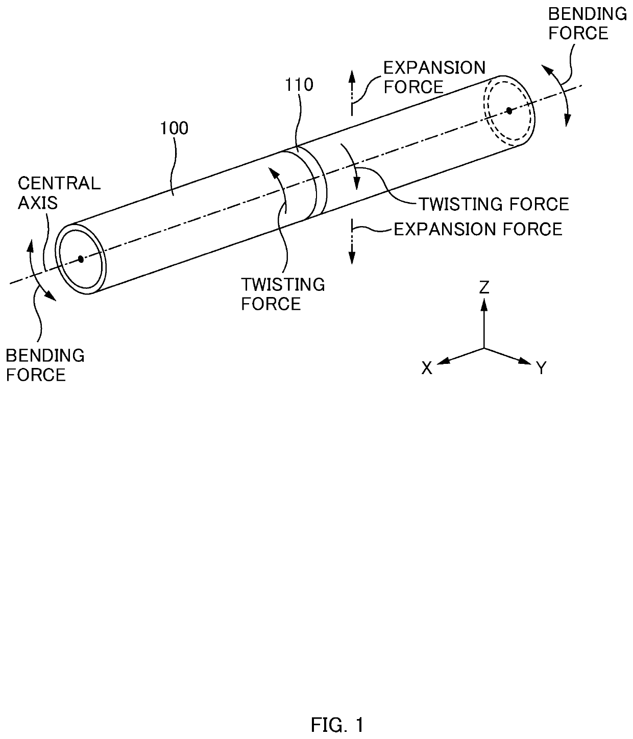
[0020]In the above-described process of power generation, the high temperature and high pressure fluid or gas (hereinafter, referred to as “thermal fluid”) circulates through boiler tubes. Since thermal stress is generated in such boiler tubes by thermal fluid, creep-fatigue damage may be caused therein.

[0021]Thermal stress indicates stress that acts on the boiler tube according to such a force that the boiler tube will expand or contract, for example, with heat obtained from the thermal fluid circulating through the boiler tube. In spe...

Example

Second Embodiment

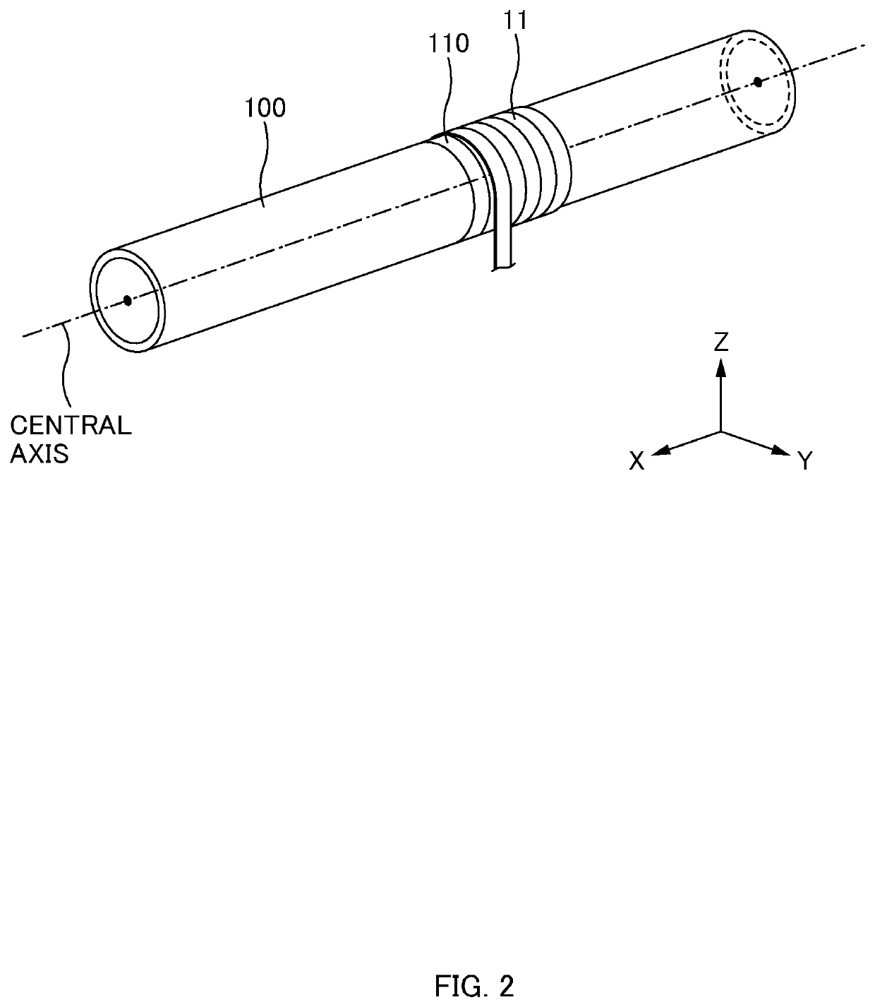
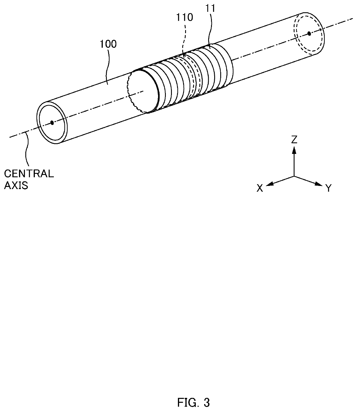
[0047]The reinforcement device 10 according to a second embodiment is different, in only the structure of a reinforcement steel plate (sheet) 22, from the reinforcement device 10 according to the first embodiment. Thus, in the following description, only a reinforcement steel plate 22 will be described, while the descriptions of the steel strip 11 and a usage procedure is omitted as being the same as those in the reinforcement device 10 according to the first embodiment. Further, for convenience of explanation, when describing the reinforcement steel plate 22 according to the second embodiment with reference to FIGS. 2 to 8, description will be given with the reinforcement steel plate 12 according to the first embodiment in FIGS. 2 to 8 being substituted with the reinforcement steel plate 22 according to the second embodiment.

==Configuration of Reinforcement Device==

[0048]As illustrated in FIGS. 2 to 9, the reinforcement device 10 according to the second embodiment ...


PUM


Abstract

A boiler tube reinforcement device reinforces a boiler tube including a first boiler tube, a second boiler tube, and a weld portion joining edges of the first boiler tube and the second boiler tube together. The boiler tube reinforcement device includes: a sheet-shaped first steel plate wrapped in a region including the weld portion of the boiler tube and reinforces the boiler tube, the first steel plate including a plurality of bending portions, the bending portions being formed along a longitudinal direction of the boiler tube at regular intervals along a circumferential direction of the boiler tube, wherein the first steel plate is wrapped in the region of the boiler tube.

Description

TECHNICAL FIELD[0001]The present disclosure relates to a boiler tube reinforcement device and a boiler tube reinforcement method.BACKGROUND ART[0002]For example, a boiler for power generation that is installed in a thermal power plant to rotate a turbine includes: an economizer that preheats boiler feed water; a water-cooled wall that forms a housing of the boiler and converts the boiler feed water into saturated steam; a superheater that further heats the saturated steam to be converted into superheated steam; a reheater that reheats steam from the turbine to be supplied to the turbine again; pipes that guide steam from the superheater and reheater to a steam turbine; and the like. The above pipes that guide steam from the superheater and reheater to the steam turbine are constituted by boiler tubes made of heat-resistant steel (for example, low-alloy steel). When the boiler for power generation is activated, high temperature and high pressure steam flows through the boiler tubes, ...

Claims


Application Information

Patent Timeline
IPC IPC(8): F22B37/10F16L13/04F16L57/02
CPCF22B37/108F16L13/04F16L57/02F16L57/00F22B37/10
Inventor MATSUMURA, HIDEONISHIDA, HIDETAKA
Owner THE CHUGOKU ELECTRIC POWER CO INC
Why Eureka
Try Eureka