
Code Management System and Code Management Method

Active Publication Date: 2020-07-30
HITACHI LTD
View PDF0 Cites 3 Cited by
  • Summary
  • Abstract
  • Description
  • Claims
  • Application Information

AI Technical Summary

Benefits of technology

The patent aims to improve the ease of using software generated by a visual programming tool. The technical effect of the invention is to make it even more convenient for developers to reuse software components.

Problems solved by technology

This is difficult work for a developer with inadequate knowledge of software development.
Moreover, even for a developer who is well versed in software development, the steps of reading code and searching for reusable code represent a large overhead in software development.

Method used


Image

  • Code Management System and Code Management Method
  • Code Management System and Code Management Method
  • Code Management System and Code Management Method

Examples


example 1

[0025]This embodiment example illustrates a method in which, in a system capable of registering, in a code management tool, source code (hereinafter called code) of software generated using a visual programming tool and of reusing the source code, by linking flow images of code displayed via the visual programming tool to the code and registering the flow images in the management tool, the flow images are applied as information upon selecting reusable code.

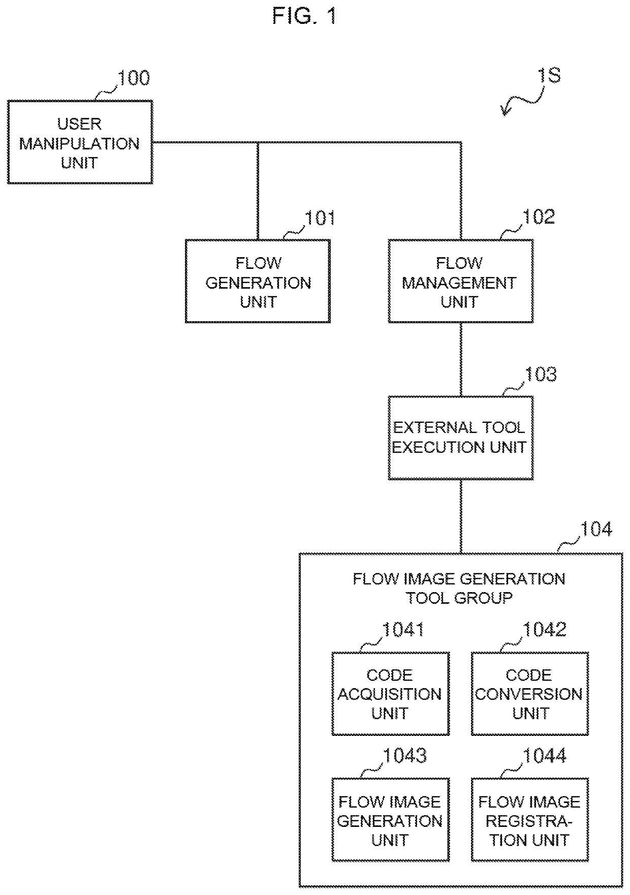
[0026]First, a configuration example of the code management system according to this embodiment example will be described by using FIG. 1. FIG. 1 is a diagram illustrating a configuration example of the code management system according to Example 1.

[0027]As illustrated in FIG. 1, a code management system 1S according to this embodiment example includes a user manipulation unit 100, a flow generation unit 101, a flow management unit 102, an external tool execution unit 103, and a flow image generation tool group 104. In addition, t...

example 2

[0070]As illustrated in FIG. 4, when a plurality of flows exist upon displaying flow images as code supplementary information, sometimes it is desirable to display only a representative flow. For example, there are cases such as those where the flows are nested, and it is desirable to display only a top-level main flow. An Example 2 in which a display of only the top-level main flow is realized is described hereinbelow by using the flowchart in FIG. 9. FIG. 9 is an example of a flowchart showing a process flow including the selection of flows saved as flow images when a plurality of flows exist, in processing of the code management system according to Example 2.

[0071]When compared with the processing of the code management system according to Example 1, the processing of the code management system according to Example 2 illustrated in FIG. 9 is the same except for the fact that steps S5031 and S5032 are executed between steps S503 and S504. Descriptions of parts overlapping with the...

example 3

[0075]Means for displaying only a representative flow image as code supplementary information is not limited to a method, as illustrated in the flowchart in FIG. 9 of Example 2, where a target flow is selected in the step following step S503 in which flow image screenshots are acquired. Another method for selecting a target flow will be described hereinbelow as an Example 3, using the flowchart in FIG. 10. FIG. 10 is a diagram illustrating an example of a flowchart showing a process flow including the selection of flow images displayed together with code when a plurality of flow images exist in the flow management repository, in processing of the code management system according to Example 3.

[0076]When compared with the processing of the code management system according to Example 1, the processing of the code management system according to Example 3 illustrated in FIG. 10 is the same except for the fact that steps S5051 to S5054 are executed after step S505 and the processing of th...


PUM


Abstract

The convenience of reusing software generated by a visual programming tool is further improved. A code management system includes a flow generation unit that creates a process flow based on user manipulation and generates code based on the created process flow, a flow management unit that saves the code generated by the flow generation unit, a code acquisition unit that acquires code in response to the code being saved in the flow management unit, a code conversion unit that converts the code acquired by the code acquisition unit to a process flow diagram, a flow image generation unit that generates a flow image of the process flow diagram converted by the code conversion unit, and a flow image registration unit that registers the flow image generated by the flow image generation unit in the flow management unit in association with the code prior to conversion to the process flow diagram by the code conversion unit.

Description

TECHNICAL FIELD[0001]The present invention relates to a code management system and a code management method.BACKGROUND ART[0002]Programming tools include visual programming tools that enable software to be developed by describing model diagrams without writing source code. One such example is Node-RED (https: / / nodered.org / ). In software development that uses visual programming tools, information corresponding to the intended use, the environment and other circumstances is configured as attribute values (properties) for nodes represented by various processes, and a series of processes are described as a flow each time nodes are wired together. By using such visual programming tools, software developers are able to develop software for performing intuitively designed processes even without adequate knowledge of software development.[0003]Furthermore, in the software development field, there are endeavors to shorten development periods by frequently reusing code. In such cases, reusabl...

Claims


Application Information

Patent Timeline
IPC IPC(8): G06F8/34G06F8/75
CPCG06F8/34G06F8/75G06F8/36
Inventor NISHIDA, TOSHIOKINOSHITA, JUNJIHATASAKI, KEISUKE
Owner HITACHI LTD
Learn More