
System and method for assembling components of a gas turbine engine

Inactive Publication Date: 2020-08-06
ROLLS ROYCE PLC
View PDF0 Cites 2 Cited by
  • Summary
  • Abstract
  • Description
  • Claims
  • Application Information

AI Technical Summary

Benefits of technology

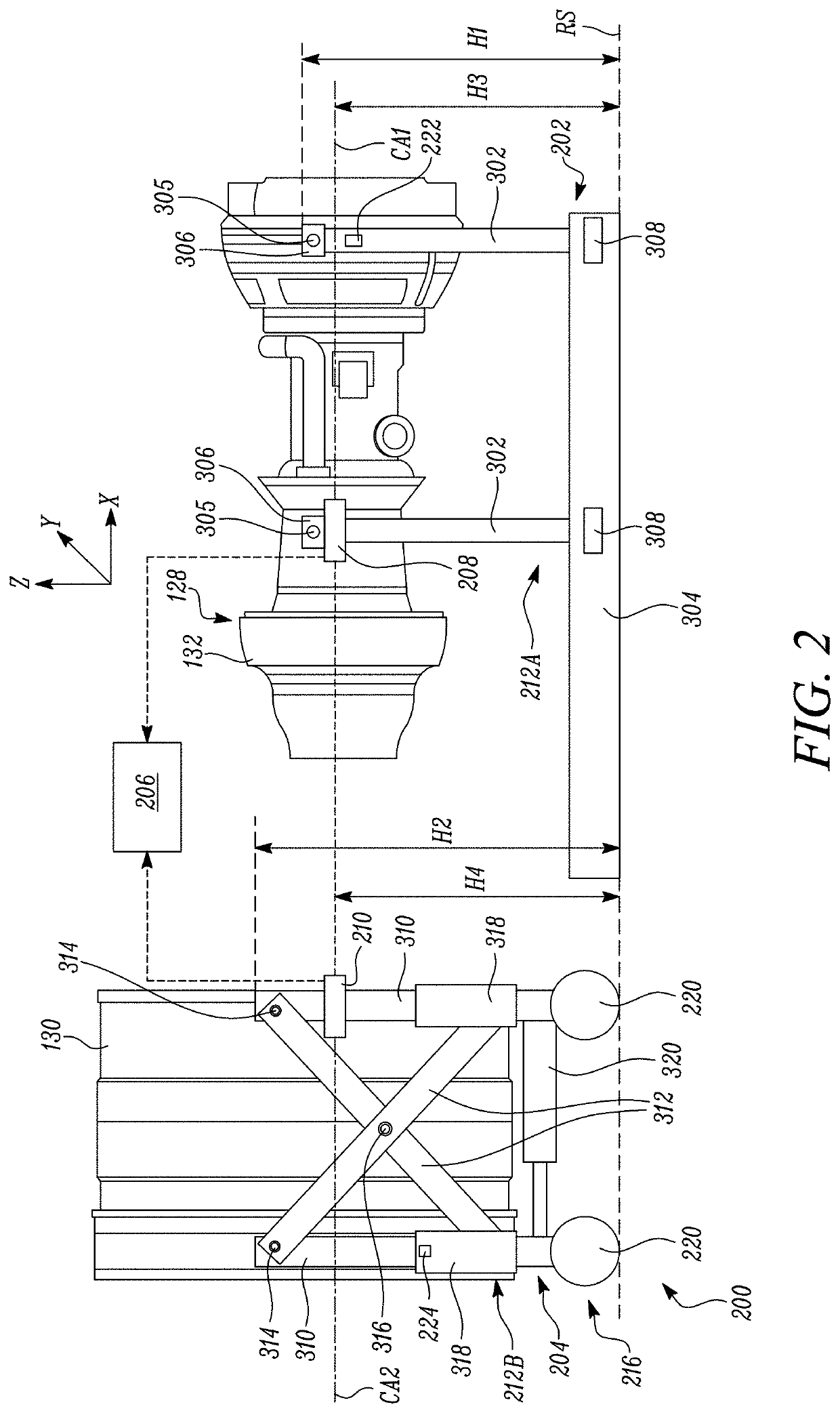
The patent describes a system and method for automated alignment and guidance of a core engine and fan case during assembly. This system can make the assembly process faster, reliable, consistent, and with minimal manpower requirements compared to conventional manual processes. It can also accurately provide small clearances between the core engine and fan case, even on uneven surfaces or in remote locations. The system can improve engine assembly efficiency and reduce the risk of misalignment and damage during assembly. The time saved by using the system can allow personnel to work on other important tasks. The system is especially useful for assembling turbofan engines with high bypass ratio. The core engine and fan case supports may have level sensors that enable self-levelling, allowing the supports to automatically adjust their position based on signals from the sensors. Overall, the system and method provide a more efficient and reliable way to assemble core engines and fans.

Problems solved by technology

Small clearances between components make such manual assembly difficult and time consuming.
Manual assembly may further increase a risk of misalignment and damage during assembly.
Additionally, manual assembly can only be performed in a workshop environment with a substantially even ground surface.

Method used


Image

  • System and method for assembling components of a gas turbine engine
  • System and method for assembling components of a gas turbine engine
  • System and method for assembling components of a gas turbine engine

Examples


Embodiment Construction

[0036]Aspects and embodiments of the present disclosure will now be discussed with reference to the accompanying figures. Further aspects and embodiments will be apparent to those skilled in the art.

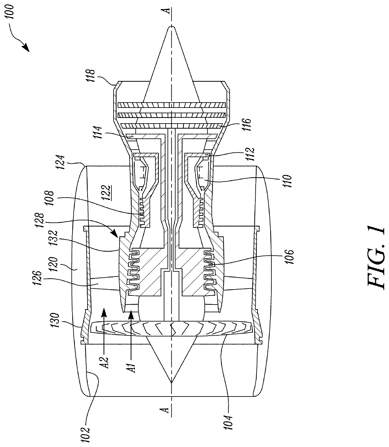
[0037]With reference to FIG. 1, a gas turbine engine is generally indicated at 100, having a principal and rotational axis A-A. The gas turbine engine 100 comprises, in axial flow series, an air intake 102, a propulsive fan 104, an intermediate pressure compressor 106, a high-pressure compressor 108, combustion equipment 110, a high-pressure turbine 112, an intermediate pressure turbine 114, a low-pressure turbine 116 and a core engine exhaust nozzle 118. A nacelle 120 generally surrounds the gas turbine engine 100 and defines the air intake 102, a bypass duct 122 and a bypass exhaust nozzle 124. A row of guide vanes 126 is positioned in the bypass duct 122 rearward of the propulsive fan 104.

[0038]During operation, air entering the air intake 102 is accelerated by the propulsive fan 104 ...


PUM


Abstract

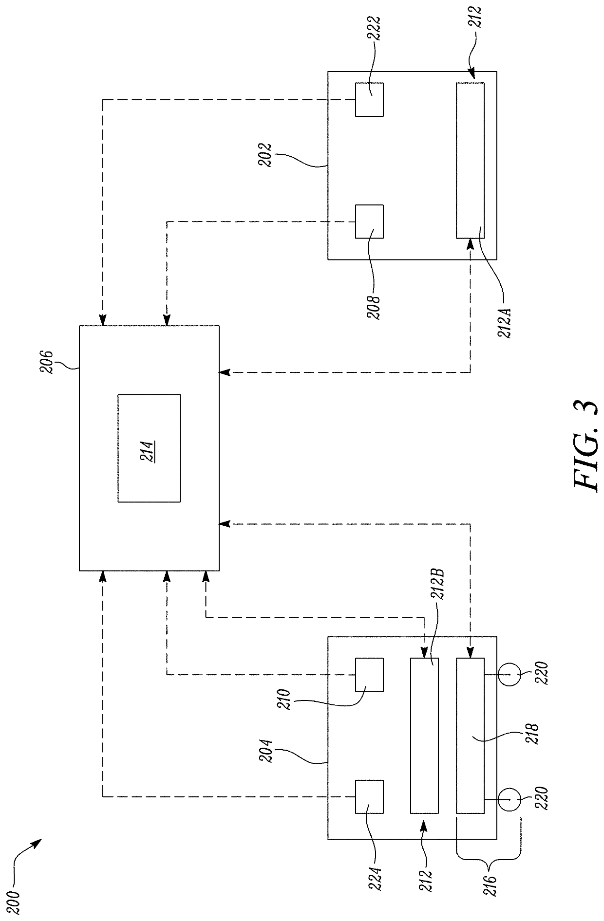
A system and a method for assembling a core engine and a fan case of a gas turbine engine. The system includes a core engine support that detachably supports the core engine. The core engine support includes at least one core engine alignment sensor. The system further includes a fan case support that detachably supports the fan case. The fan case support includes at least one fan case alignment sensor. The system further includes a computer-controllable unit configured to align the core engine support and the fan case support based on signals from the at least one core engine alignment sensor and the at least one fan case alignment sensor. The computer-controllable unit is further configured to guide a movement of at least one of the core engine support and the fan case support to couple the core engine with the fan case.

Description

CROSS-REFERENCE TO RELATED APPLICATIONS[0001]This specification is based upon and claims the benefit of priority from United Kingdom patent application number GB 1901396.0 filed on Feb. 1, 2019, the entire contents of which are incorporated herein by reference.BACKGROUNDField of the Disclosure[0002]The present disclosure concerns a system and a method for assembling components of a gas turbine engine.Description of the Related Art[0003]A gas turbine engine with bypass (i.e., a turbofan) typically includes a fan case and a core engine. The fan case and the core engine have to be assembled with each other during manufacture. The fan case and the core engine may subsequently be separated for carrying out various tasks, such as servicing, repair and replacement of one or more components. Generally, the fan case and the core engine have to be accurately aligned and levelled before assembly. The assembling process is typically performed manually. Small clearances between components make s...

Claims


Application Information

Patent Timeline
IPC IPC(8): F01D25/28F01D25/24G05B19/402
CPCG05B2219/2629F05D2240/90F01D25/24F01D25/28F05D2220/32G05B19/402F05D2230/64B23P19/00B23P19/105F01D25/285F05D2230/68F05D2270/804
Inventor COOPER, JOSEPH B.
Owner ROLLS ROYCE PLC
Learn More