Eureka AIR delivers breakthrough ideas for toughest innovation challenges, trusted by R&D personnel around the world.

Universal socket structure

a socket and universal technology, applied in the direction of screwdrivers, wrenches, shafts and bearings, etc., can solve the problems of easy wear and breakage, easy wear and tear, and loose parts in use, so as to reduce manufacturing time and cost, simplify assembly steps, and reduce manufacturing costs

Active Publication Date: 2020-08-06
TSAI JHIH SHENG
View PDF0 Cites 2 Cited by
  • Summary
  • Abstract
  • Description
  • Claims
  • Application Information

AI Technical Summary

Benefits of technology

The present invention provides a universal socket structure that can simplify assembly and reduce manufacturing time and cost. It also solves the problem of pin and sphere perforation wear and breakage after use. Additionally, it simplifies edge trimming of a protrusion and enlarges rotating angle of a joint member.

Problems solved by technology

1. For the joint member 91 consisting of the pin 93 passing through the perforation 921 of the spherical head 92, because the pin 93 and the spherical head 92 are two independent components, they must be manufactured separately, and their mating precision is controlled separately. In the assembly, the assembly step of inserting the pin 93 in the perforation 921 of the spherical head 92 must be performed first. On the premise that labor costs are increasing, many manufacturing and assembly steps will inevitably lead to an increase in manufacturing and assembly costs, which is not beneficial for the competition of products.
2. For the joint member 91 consisting of the pin 93 passing through the perforation 921 of the spherical head 92, because the pin 93 and the spherical head 92 are two independent components, when in use, the pin 93 and the perforation 921 of the spherical head 92 are easily worn and broken. Once the pin 93 and the perforation 921 of the spherical head 92 are worn and broken, the parts may be loose in use, and they may be thrown out during high-speed rotation.

Method used


Image

  • Universal socket structure
  • Universal socket structure
  • Universal socket structure

Examples


Embodiment Construction

[0019]Embodiments of the present invention will now be described, by way of example only, with reference to the accompanying drawings.

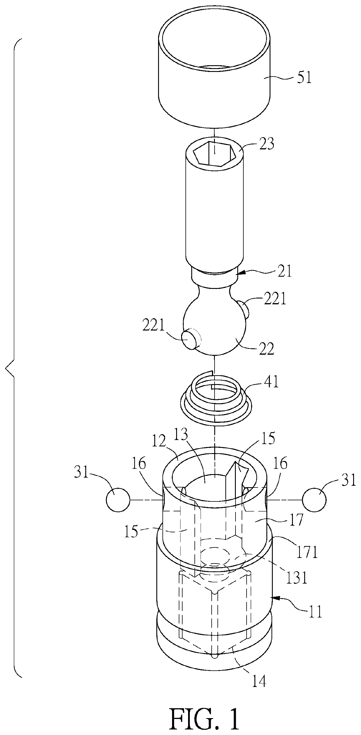
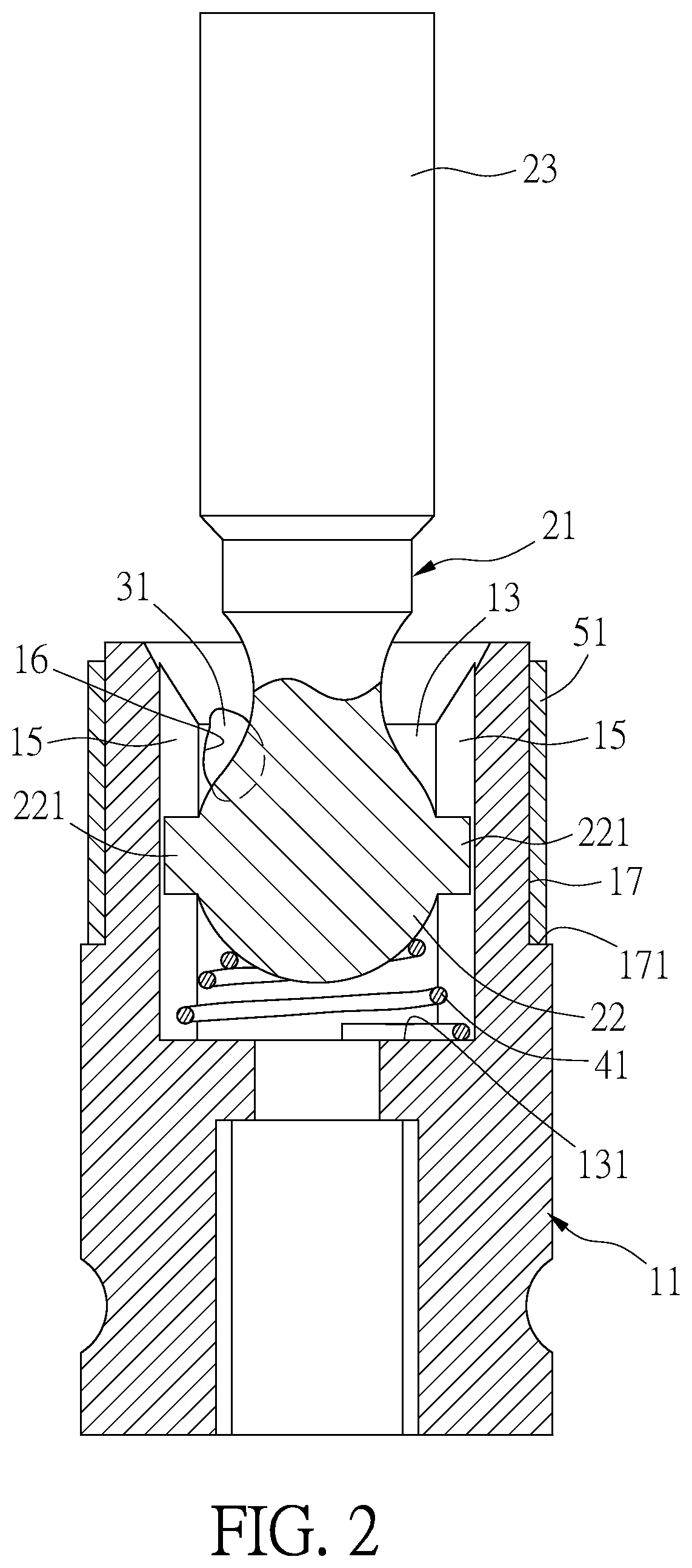
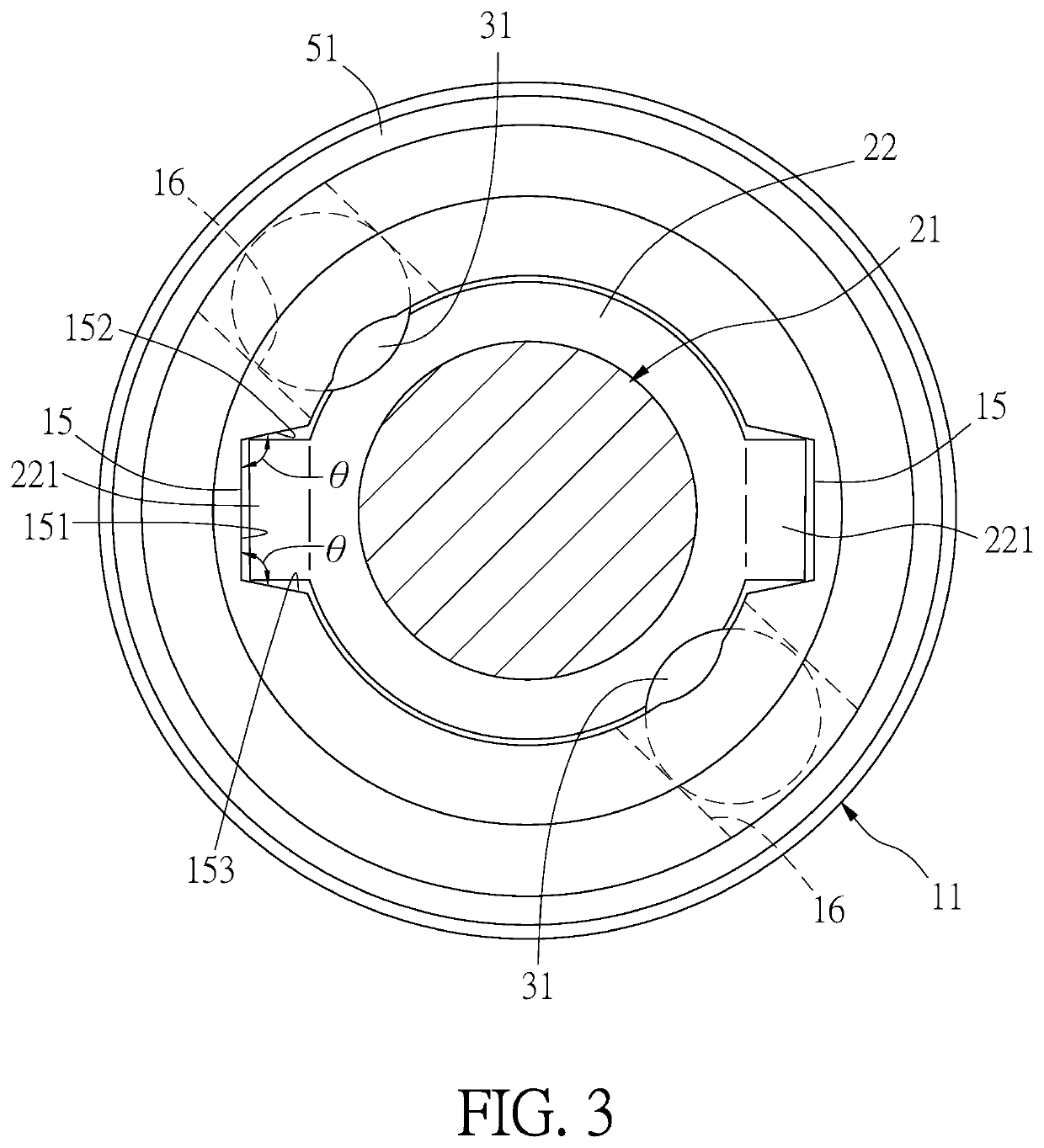
[0020]Referring to FIG. 1, FIG. 2 and FIG. 3, a universal socket structure in accordance with a first embodiment of the present invention comprises a female seat 11, a joint member 21, two engaging members 31, an elastic member 41, and an annular buckle 51.

[0021]The female seat 11 has a cylindrical shape extending along an axial direction. One end of the female seat 11 is defined as a coupling end 12. The coupling end 12 is recessed to form an accommodating trough 12 in a cylindrical shape with an outward opening. Another end of the female seat 11 is defined as a receiving end 14. The receiving end 14 is recessed to form a square trough for receiving driving tools (not shown), such as hand tools or pneumatic / electric wrenches. Two opposite sides of the accommodating trough 13 are formed with a pair of grooves 15 extending along the axial direction of ...


PUM


Abstract

A universal socket structure includes a female seat, a joint member, at least one engaging member, and an elastic member. A coupling end the female seat is recessed to form an accommodating trough. Two opposite sides of the accommodating trough are formed with grooves extending along an axial direction of the female seat. The female seat has at least one coupling portion. The joint member has one end formed with a spherical head. Two opposite sides of the spherical head has protrusions protruding from an outer periphery of the spherical head. The spherical head is accommodated in the accommodating trough. The protrusions are accommodated in the grooves. The engaging member is disposed in the coupling portion and movable from the coupling portion toward the accommodating trough. The elastic member is disposed in the accommodating trough for pushing and supporting the spherical head to engage with the engaging member.

Description

FIELD OF THE INVENTION[0001]The present invention relates to a drive socket, and more particularly to a universal socket structure for connecting a hand tool or a pneumatic / electric tool.BACKGROUND OF THE INVENTION[0002]Universal sockets are attached to hand tools or pneumatic / electric tools for locking or unlocking bolts. As shown in FIG. 6, a universal socket structure disclosed in Taiwan Patent No. 1397456 includes a joint member 91. One end of the joint member 91 is formed with a spherical head 92. A pin 93 is inserted through a perforation 921 of the spherical head 92, and two ends of the pin 93 extend out of the outer circumference of the spherical head 92. When the spherical head 92 of the joint member 91 is accommodated in an accommodating trough 95 of a female seat 94, the two ends of the pin 93 are engaged in two longitudinal grooves 951 of the accommodating trough 95. The joint member 91 can be obliquely rotated relative to the female seat 94 to change its connection angl...

Claims


Application Information

Patent Timeline
Patent Type & Authority Applications(United States)
IPC IPC(8): F16C11/06
CPCF16C11/0623B25B23/0014B25B13/06F16D3/2052
Inventor TSAI, JHIH SHENG
Owner TSAI JHIH SHENG
Why Eureka
Eureka Blog
Learn More