
A Magnetic Bearing Assembly As Well As A Linear Guideway Assembly Implementing One Or More Such Magnetic Bearing Assemblies

a technology of magnetic bearings and linear guides, which is applied in the direction of bearings, instruments, electrical equipment, etc., can solve the problems of limited design dimensions, technological and constructional constraints, and the development of magnetic bearings of significant weight, size and cost,

Active Publication Date: 2020-08-06
VDL ENABLING TECH GRP BV
View PDF0 Cites 3 Cited by
  • Summary
  • Abstract
  • Description
  • Claims
  • Application Information

AI Technical Summary

Benefits of technology

The patent text describes a magnetic bearing system that allows for precise control of the gap between two rigid bodies, and thus the contactless linear displacement of these bodies relative to each other. The system includes a setting module that allows for a presetting of the constant pre-load in the opposite direction of the attraction force, which further allows for control of the net force exerted on the magnetic bearing module. This helps to statically balance forces and minimize energy dissipation in different applications, improving the overall efficiency of the magnetic bearing system.

Problems solved by technology

The main challenges of applying magnetic bearings in high-tech in-vacuum systems lie in minimization of heat dissipation in the coils, minimizing eddy-current effects, implementation of a stable control system and linearization of the typically non-linear characteristics.
Although utilized in other fields, further development of magnetic bearing applications on a commercial scale in for example high cleanliness substrate handling robotics suffer from technological and constructional constraints.
Commonly known magnetic bearing applications are characterized by their limited design dimensions, whereas upscale implementation of magnetic bearing applications require the development of magnetic bearings of significant weight, size and cost, whereas conventional rolling element bearings are still available for similar purposes.

Method used


Image

  • A Magnetic Bearing Assembly As Well As A Linear Guideway Assembly Implementing One Or More Such Magnetic Bearing Assemblies
  • A Magnetic Bearing Assembly As Well As A Linear Guideway Assembly Implementing One Or More Such Magnetic Bearing Assemblies
  • A Magnetic Bearing Assembly As Well As A Linear Guideway Assembly Implementing One Or More Such Magnetic Bearing Assemblies

Examples


Embodiment Construction

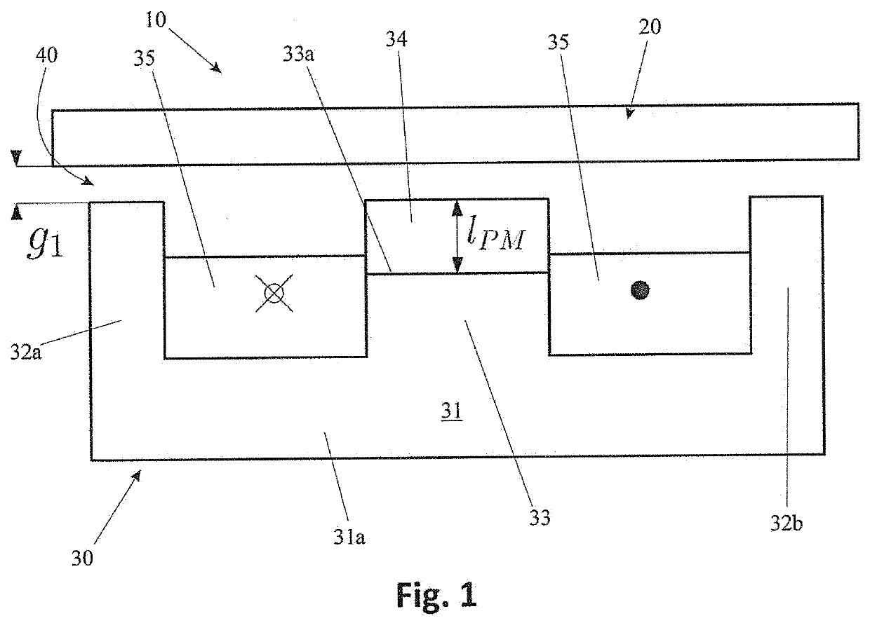
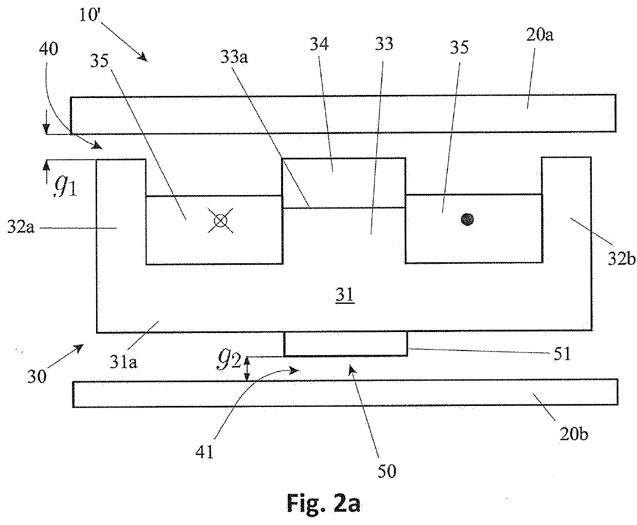
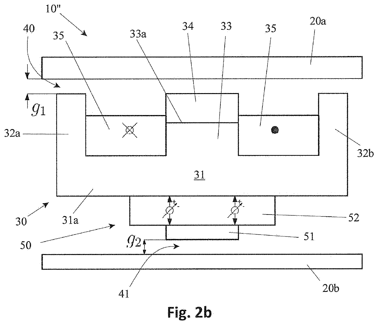
[0006]The invention aims to provide a solution for the above identified problems, allowing linear displacement of a rigid body relative to another rigid body along a linear displacement path and in particular allowing control of a translational degree of freedom of a rigid body relative to another rigid body, said magnetic bearing assembly comprising:[0007]at least one magnetic bearing module being mounted to one of said rigid bodies and consisting of at least:[0008]a ferromagnetic core;[0009]a first magnetic element positioned on a first side of said ferromagnetic core;[0010]a coil being wound around said ferromagnetic core;[0011]at least a first static back iron being mounted to the other one of said rigid bodies and positioned, during use, at some gap distance from said one bearing module.

[0012]As such a magnetic bearing assembly is obtained, which allows a contactless linear displacement of a rigid body relative to another rigid body, without friction, which results in no partic...


PUM


Abstract

The invention relates to a magnetic bearing assembly for contactless linear displacement of a rigid body relative to another rigid body along a linear displacement path.The invention also relates to a linear guideway assembly implementing one or more such magnetic bearing assemblies.The invention aims to provide a solution for the above identified problems, allowing linear displacement of a rigid body relative to another rigid body along a linear displacement path and in particular allowing control of a translational degree of freedom of a rigid body relative to another rigid body, said magnetic bearing assembly comprising:at least one magnetic bearing module being mounted to one of said rigid bodies and consisting of at least:a ferromagnetic core;a first magnetic element positioned on a first side of said ferromagnetic core;a coil being wound around said ferromagnetic core;at least a first static back iron being mounted to the other one of said rigid bodies and positioned, during use, at some gap distance from said one bearing module.

Description

FIELD OF THE INVENTION[0001]The invention relates to a magnetic bearing assembly for contactless linear displacement of a rigid body relative to another rigid body along a linear displacement path.[0002]The invention also relates to a linear guideway assembly implementing one or more such magnetic bearing assemblies.BACKGROUND OF THE INVENTION[0003]Magnetic bearing assemblies or in short magnetic bearings could provide an advantageous alternative to conventional rolling element bearings. Given that magnetic bearings are contactless, there is no mechanical friction and thus very little particle generation. Moreover, there is no need for lubrication which enables in vacuum operation without significant outgassing of molecular contamination. These aspects make that contamination seals can be omitted. The main challenges of applying magnetic bearings in high-tech in-vacuum systems lie in minimization of heat dissipation in the coils, minimizing eddy-current effects, implementation of a ...

Claims


Application Information

Patent Timeline
IPC IPC(8): F16C32/04
CPCF16C32/0472F16C29/00F16C32/0465H01L21/67709G03F7/70716
Inventor PEIJNENBURG, ANTONIUS THEODORUS ADRIANUSBAADE, RICK
Owner VDL ENABLING TECH GRP BV
Learn More