Optical assembly for a lidar system, lidar system and working apparatus

Active Publication Date: 2020-08-06
ROBERT BOSCH GMBH
View PDF0 Cites 0 Cited by
  • Summary
  • Abstract
  • Description
  • Claims
  • Application Information

AI Technical Summary

Benefits of technology

The present invention is directed to an optical assembly that has a compact design. One way to achieve this is by using receiver optics that have a beam path that is folded numerous times, such as by two or three secondary mirrors. These secondary mirrors may be concave mirrors or reflective bandpass filters. The technical effect is that the optical assembly has a more efficient use of space, resulting in a more compact design.

Problems solved by technology

It is a disadvantage of conventional LiDAR systems and the optical assemblies thereof that, in the case of coaxial beam paths of the transmitter optics and the receiver optics on the beam output side, respectively the beam input side, beam splitters are usually used, which, in the case of line illumination, result in an enlarged installation space of the LiDAR system, in a decreased receive aperture and / or in a reduction in the beam diameter upon exit of the beam.

Method used


Image

  • Optical assembly for a lidar system, lidar system and working apparatus
  • Optical assembly for a lidar system, lidar system and working apparatus
  • Optical assembly for a lidar system, lidar system and working apparatus

Examples


Embodiment Construction

[0024]Exemplary embodiments and the technical background of the present invention are described in detail in the following with reference to FIG. 1 through 10. The same reference numerals denote identical and equivalent, as well as same or functionally equivalent elements and components. The designated elements and components are not described in detail in every instance thereof.

[0025]The illustrated features and further properties may be isolated from one another in any form and arbitrarily combined with one another without departing from the spirit and scope of the present invention.

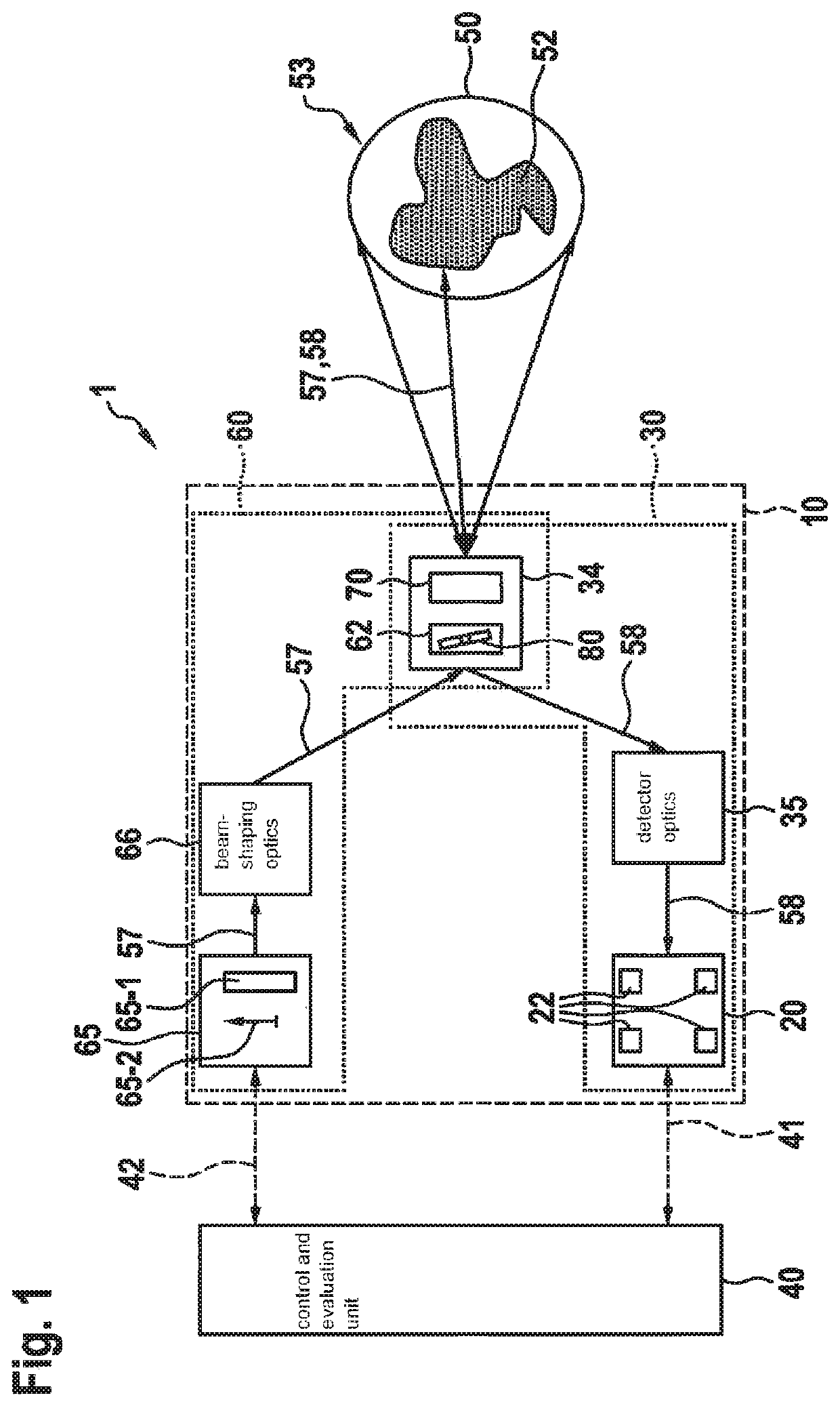
[0026]In the form of a schematic block diagram, FIG. 1 shows a specific embodiment of LiDAR system 1 according to the present invention on the basis of a specific embodiment of optical assembly 10 according to the present invention.

[0027]LiDAR system 1 according to FIG. 1 has a transmitter optics 60, which is fed by a light source unit 65, for example, which has a laser as a line light source 65-1 havi...


PUM


Abstract

An optical assembly for a LiDAR system is described. The optical assembly includes receiver optics and transmitter optics, designed to include partially coaxial beam paths; a line light source having a line orientation, which is configured, in particular within the range of a field of view of the underlying LiDAR system; and a deflection unit in a transition region from a common coaxial region to a separate biaxial region of the beam paths of the receiver optics and of the transmitter optics for biaxially splitting off a detector-side portion of the beam path of the receiver optics. The deflection unit has a hole mirror having an elongated hole that has a greater extent in a direction of longitudinal extent and a lesser extent in a direction of transverse extent. The direction of longitudinal extent of the elongated hole is oriented orthogonally to the line orientation of the line light source.

Description

FIELD[0001]The present invention relates to an optical assembly for a LiDAR system, a LiDAR system as such, as well as to a working apparatus and, in particular a vehicle.BACKGROUND INFORMATION[0002]In the use of working apparatuses, vehicles, and other machines and systems, operational assistance systems or sensor arrays are increasingly used to detect the operating environment. Besides radar-based systems or ultrasound-based systems, light-based detection systems, what are generally referred to as LiDAR (light detection and ranging) systems, for example, are increasingly being used.[0003]It is a disadvantage of conventional LiDAR systems and the optical assemblies thereof that, in the case of coaxial beam paths of the transmitter optics and the receiver optics on the beam output side, respectively the beam input side, beam splitters are usually used, which, in the case of line illumination, result in an enlarged installation space of the LiDAR system, in a decreased receive apertu...

Claims


Application Information

Patent Timeline
IPC IPC(8): G01S7/481G01S17/931
CPCG01S17/931G01S7/4817G01S7/4812G01S7/4815G02B5/005G02B26/10
Inventor HOLLECZEK, ANNEMARIESPARBERT, JANBOGATSCHER, SIEGWARTSPIESSBERGER, STEFANPETERSEIM, TOBIAS
Owner ROBERT BOSCH GMBH
Why Eureka
Try Eureka