Augmented Reality Display

a technology of augmented reality and display, applied in the field of displays, can solve problems such as bulky structur

Active Publication Date: 2020-08-06
LUMUS LTD
View PDF0 Cites 31 Cited by
  • Summary
  • Abstract
  • Description
  • Claims
  • Application Information

AI Technical Summary

Benefits of technology

[0009]According to a further feature of an embodiment of present invention, the projector comprises an optical aperture expansion arrangement for projecting an imag

Problems solved by technology

The geometrical requirements for the oblique angle of

Method used


Image

  • Augmented Reality Display
  • Augmented Reality Display
  • Augmented Reality Display

Examples


Embodiment Construction

[0036]The present invention is a display for providing an image to an eye of an observer.

[0037]The principles and operation of displays according to the present invention may be better understood with reference to the drawings and the accompanying description.

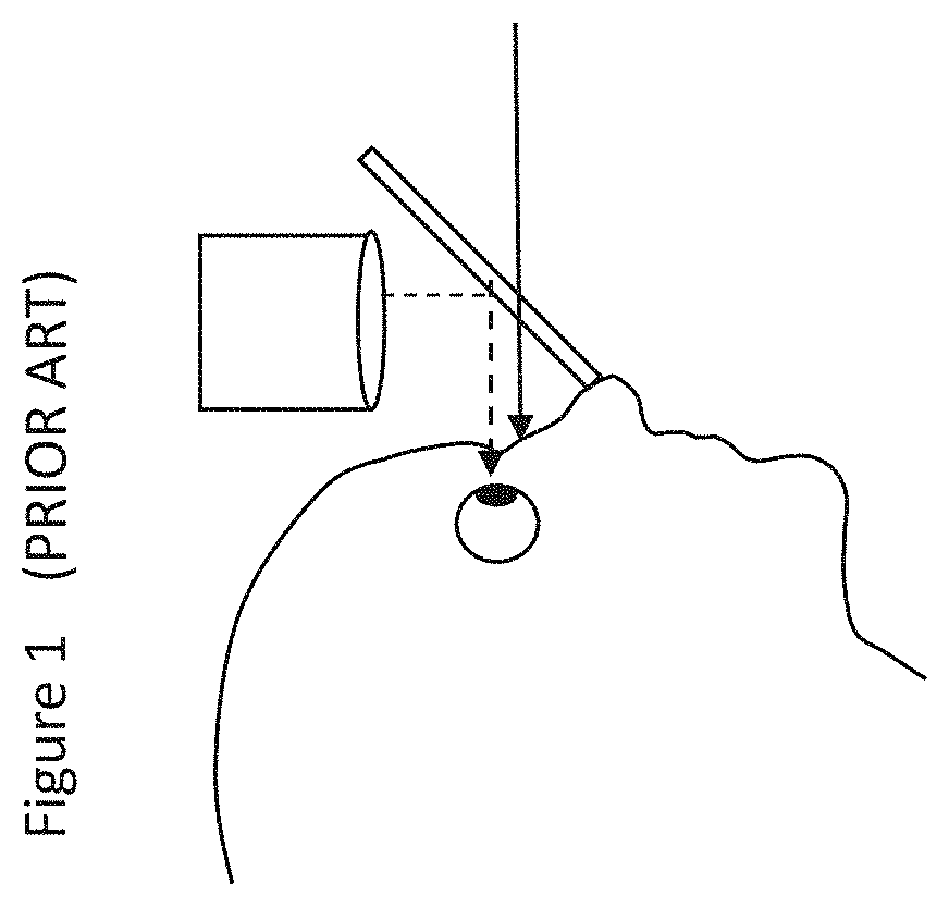
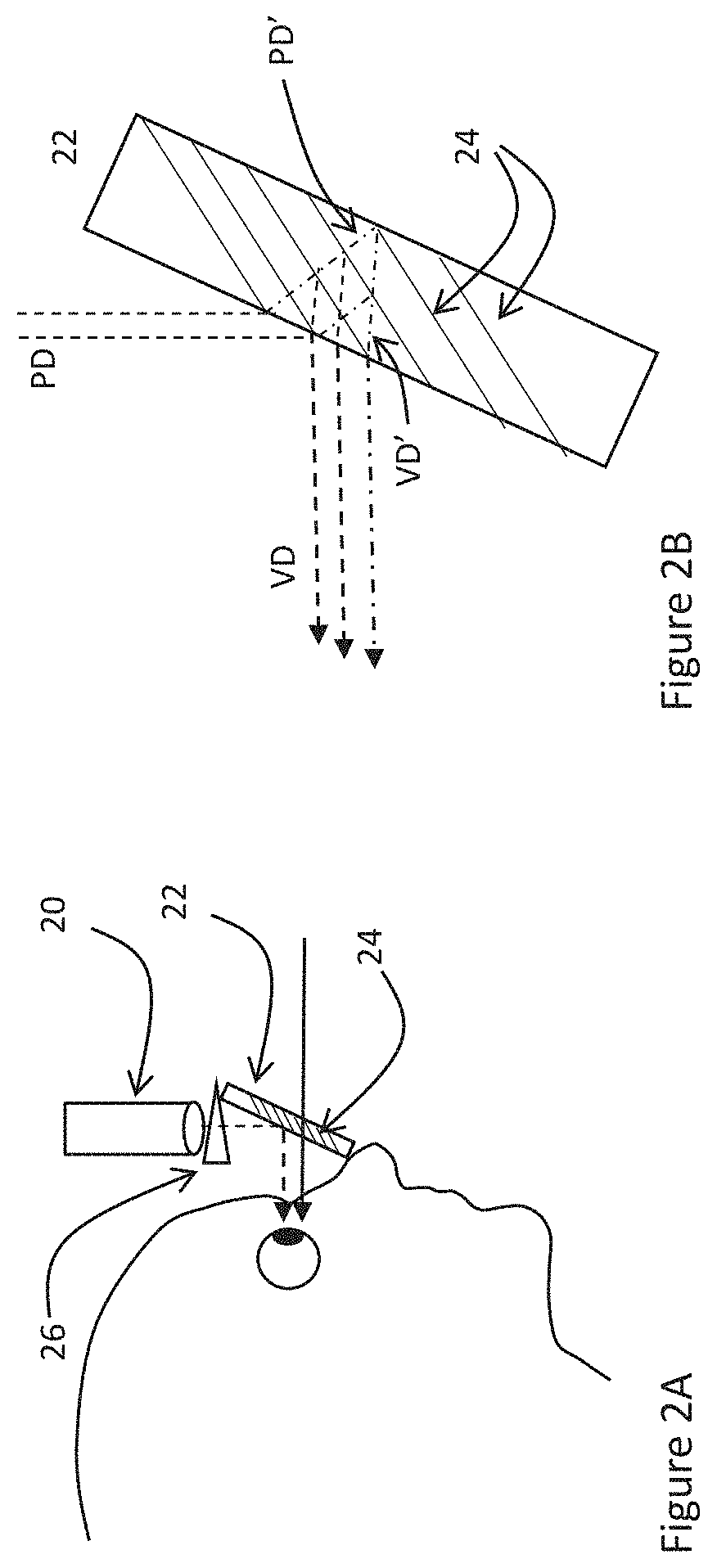
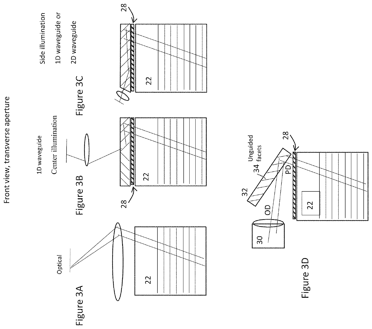
[0038]Referring now to the drawings, FIGS. 2A-10C illustrate various implementations of a display, constructed and implemented according to the teachings of certain embodiments of the present invention, for providing an image to an eye of an observer along a viewing direction VD. In general terms, the display includes an image projector 20 (or 60 or 97, according to the different examples) projecting collimated image illumination along a projection direction PD, and an optical element 22 (or 62, 72 or 110) formed from at least partially transparent material having first and second major surfaces. The optical element includes a plurality of partially reflective surfaces or “facets”24 (41, 52, 64, 74 or 90A), which are internal t...


PUM


Abstract

A display has an image projector projecting collimated image illumination along a projection direction, and an optical element having two major surfaces and containing partially reflective surfaces which are internal to the optical element, planar, mutually parallel and overlapping relative to the projection direction. Each ray of the collimated image illumination enters the optical element and is partially reflected by at least two of the partially reflective surfaces so as to be redirected to exit the first major surface along a viewing direction. An alternative implementation, a first reflection from one of the partially reflective surfaces redirects part of the image illumination rays so as to undergo total internal reflection at the major surfaces of the optical element. The rays are then redirected by further reflection from another of the partially reflective surfaces to exit the optical element along the viewing direction.

Description

FIELD AND BACKGROUND OF THE INVENTION[0001]The present invention relates to displays and, in particular, it concerns an augmented reality display employing free-space image projection in combination with partially reflective surfaces deployed obliquely within an optical element.[0002]Augmented reality displays are displays which provide an observer simultaneously with a visual display and a view of the real world. Examples of augmented reality displays include head-up displays, where the display is provided via a fixed window, and near-eye displays, where the display is mounted relative to an observer's head, typically either in a glasses-frame form factor or a head-mounted visor. Particularly in the context of near-eye displays, the display needs to be compact. The visibility of the real world should be unperturbed, undistorted and not obscured.[0003]Many near eye display systems utilize a beam splitter architecture in which a partial reflector is deployed at an oblique angle in fr...

Claims


Application Information

Patent Timeline
IPC IPC(8): G02B27/01F21V8/00G02B27/28
CPCG02B6/0035G02B27/0176G02B2027/015G02B27/0172G02B27/285G02B2027/0123G02B2027/0116G02B17/006G02B27/0081G02B5/08G02B5/30
Inventor DANZIGER, YOCHAYLEVIN, NAAMAHSHARLIN, ELADCHAYET, ALEXANDER
Owner LUMUS LTD
Why Eureka
Try Eureka