Method and Apparatus for Determining the Angle of Departure

a technology of angle of departure and method, applied in the field of ultrawideband communication systems, can solve the problems of significant increase in cost and computational complexity, prior art aoa approaches simply cannot work, etc., and achieve the effect of avoiding unnecessary proliferation of numbers

Active Publication Date: 2020-08-06
DECAWAVE
View PDF0 Cites 6 Cited by
  • Summary
  • Abstract
  • Description
  • Claims
  • Application Information

AI Technical Summary

Benefits of technology

[0026]In the drawings, similar elements will be similarly numbered whenever possible. However, this practice is simply for convenience of reference and to avoid unnecessary proliferation of numbers, and is not intended to imply or suggest that our invention requires identity in either function or structure in the several embodiments.

Problems solved by technology

Furthermore, it is of no relevance in such systems which specific voltage levels are selected to represent each of the logic states.
However, in general, modern RF communication devices, e.g., cell phones, have only a single antenna, and to add a second would significantly increase the cost and computational complexity.
In such applications, prior art AoA approaches simply will not work.

Method used


Image

  • Method and Apparatus for Determining the Angle of Departure
  • Method and Apparatus for Determining the Angle of Departure
  • Method and Apparatus for Determining the Angle of Departure

Examples


Embodiment Construction

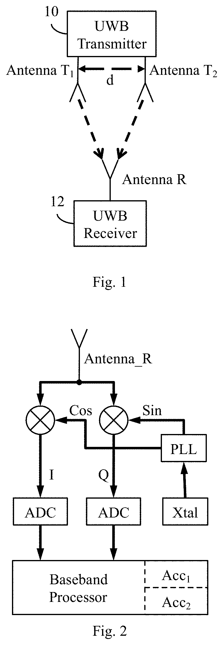
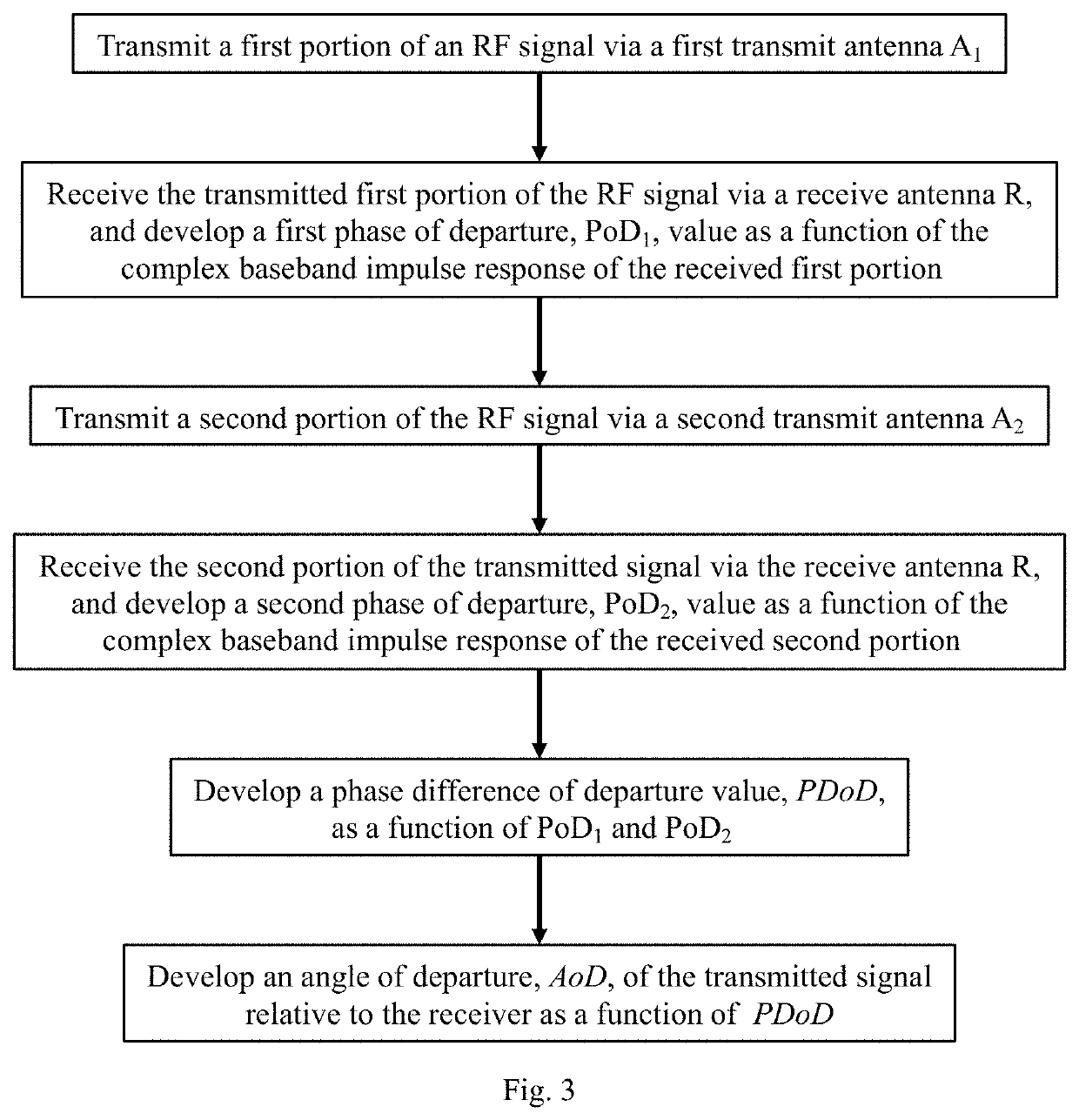
[0027]As illustrated in FIG. 1, the transmitter 10 would have two transmit antennas, antenna T1 and antenna T2, and be configured to transmit a first portion of a channel sounding signal via antenna T1 and a second portion of the channel sounding signal via antenna T2. The receiver 12, which has only a single receive antenna, Antenna_R, comprises two accumulators, Acc1 and Acc2, and is configured to accumulate into Acc1 a correlation of the first portion of the signal transmitted via antenna T1, and then accumulate into Acc2 a correlation of the second portion of the transmitted signal transmitted via antenna T2.

[0028]As is well know in this art, each of the accumulated correlations comprise respective channel impulse response estimates. From each such estimate, a respective phase of departure (“PoD”) can be calculated using known techniques. A phase difference of departure (“PDoD”) can then be calculated as a function of the difference between the PoDs of each selected transmit ant...


PUM


Abstract

An ultra-wideband (“UWB”) communication system comprising a transmitter having two transmit antennas and a receiver having a single receive antenna. Respective selected portions of the UWB signal are transmitted by the transmitter via each of transmit antennas is received at the receive antenna. By comparing the phases of the received signal portions, the phase difference of departure can be determined. From this phase difference and the known distance, d, between the transmit antennas, the Cartesian (x, y) location of the transmitter relative to the receiver can be directly determined.

Description

CROSS-REFERENCE TO RELATED APPLICATIONS[0001]The subject matter of this Application is related to U.S. Provisional Application 62 / 800,468, filed 2 Feb. 2019 (“First Parent Provisional”).[0002]The subject matter of this Application is also related to U.S. patent application Ser. No. 15 / 974,412, filed 8 May 2018 (“First Related Patent Application”).[0003]The subject matter of this Application is also related to U.S. Pat. No. 10,056,993, issued 21 Aug. 2018 (“First Related Patent”).[0004]The subject matter of the First Parent Provisional, First Related Patent Application, and the First Related patent, each in its entirety, is expressly incorporated herein by reference.[0005]This application claims priority to the First Parent Provisional, and hereby claims benefit of the filing date thereof pursuant to 37 CFR § 1.78(a)(4).BACKGROUND OF THE INVENTION1. Field of the Invention[0006]The present invention relates generally to ultra-wideband communication systems, and, in particular, to a re...

Claims


Application Information

Patent Timeline
Patent Type & Authority Applications(United States)
IPC IPC(8): H04B1/7163G01S5/06G01S5/02
CPCG01S5/0226G01S5/0221G01S5/06H04B1/7163G01S5/12H04B2201/71634
Inventor MCLAUGHLIN, MICHAELNIEWCZAS, JAROSLAWDOTLIC, IGORVERSO, BILLY
Owner DECAWAVE
Why Eureka
Try Eureka