
All-in-one converter using a low-speed optical module on a high-speed switch

a technology of optical modules and converters, applied in the field of optical modules in optical communication, can solve the problems of inconvenient use, inability to directly use low-speed optical modules in high-speed switches, and occupy a lot of space, and achieve the effect of avoiding conflicts between converters and modules, and reducing the number of modules

Active Publication Date: 2020-08-06
LINKTEL TECH CO LTD
View PDF0 Cites 2 Cited by
  • Summary
  • Abstract
  • Description
  • Claims
  • Application Information

AI Technical Summary

Benefits of technology

The present invention provides an all-in-one converter using a low-speed optical module on a high-speed switch, using a 25G optical module on a 100G switch, and simultaneously enabling a 10G optical module to be used on a 40G switch, which is more convenient for operators. Connectors designed with lower height to accommodate limited space within the converter and metal sheets on the upper surface of connectors to reduce crosalk of signals. The invention uses a device to solve the problem of inconvenient conversion and simultaneously satisfies two lower speed optical modules. An integrated MCU can read and write the information of the optical module and avoid address conflicts by reading the information of the converter. The converter can download information from other areas of the optical module and clear information of the module when the optical module is pulled out to prevent operator's misjudgment. These designs are more convenient for the operator.

Problems solved by technology

However, in the practical usage, a low-speed optical module cannot be directly used in a high-speed switch.
However, in this situation, four low-speed optical modules are required, which is very inconvenient to use and takes up a lot of space.

Method used


Image

  • All-in-one converter using a low-speed optical module on a high-speed switch
  • All-in-one converter using a low-speed optical module on a high-speed switch
  • All-in-one converter using a low-speed optical module on a high-speed switch

Examples


Embodiment Construction

[0037]The technical solutions in the embodiments of the present invention are clearly and completely described in the following with reference to the accompanying drawings in the embodiments of the present invention. It is apparent that the described embodiments are only a part of the embodiments of the invention, but not all of the embodiments. All other embodiments obtained by those of ordinary skill in the art based on the embodiments of the present invention without creative efforts are within the scope of the present invention.

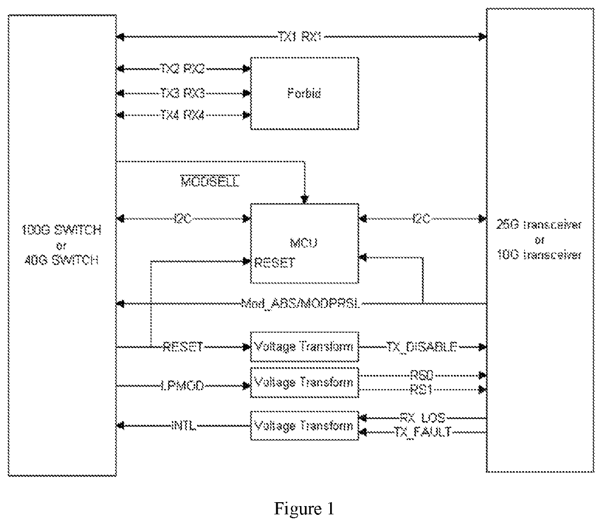
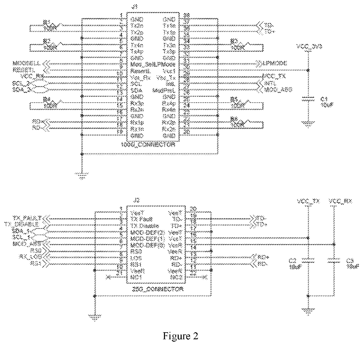
[0038]Referring FIG. 1 to FIG. 4, the present invention discloses an all-in-one converter using a low-speed optical module on a high-speed switch, which comprises a first electrical interface J1, a second electrical interface J2. The first electrical interface J1 is used to connect with a four channel high speed switch, such as a 100G or 40G switch, to realize the bidirectional transmission of signals from the switch to the converter. The second electrica...


PUM

PropertyMeasurementUnit
voltageaaaaaaaaaa
resistancesaaaaaaaaaa
resistanceaaaaaaaaaa

Abstract

The present invention relates to an all-in-one converter using a low-speed optical module on a high-speed switch. The present invention relates to the field of optical modules in optical communications. It provides a solution of using a 25G optical module on a 100G switch, and simultaneously enabling a 10G optical module to be used on a 40G switch. A first electrical interface of the converter is connected with a 100G / 40G switch, which meets the requirements of SFF-8636 protocol and realizes the bidirectional transmission of signals from the switch to the converter. A second electrical interface of the converter is connected with the optical module, which realizes the module's bidirectional transmission from the converter to the optical module. There is a signal conversion circuit inside the converter, which makes the signals of the two electrical interfaces meet the requirements of their respective protocols. An MCU is integrated inside the converter, which can read information of EEPROM inside the module, making the converter more user-friendly.

Description

CROSS-REFERENCE TO RELATED APPLICATIONS[0001]This application claims priority to Chinese Patent Applications No. 201910100248.8, filed on Jan. 31, 2019 entitled “Switching Device And Circuit For QSFP28 To SFP28 Port Backward Compatible With QSFP+ To SFP+ Port”, and No. 201920907528.5, filed on Jun. 17, 2019, entitled “All-In-One Converter Using A Low-Speed Optical Module On A High-Speed Switch” which are incorporated herein by reference in its entirety.FIELD OF THE TECHNOLOGY[0002]The present invention relates to the field of optical modules in optical communication. In particular, it relates to an all-in-one converter using a low-rate optical module on a high-speed switch.DESCRIPTION OF THE RELATED ART[0003]At present, the speed of common switches is 10G, 25G, 40G and 100G. However, due to the updating of communication equipment, 100G switches are becoming more and more commonly used. However, in the practical usage, a low-speed optical module cannot be directly used in a high-spee...

Claims


Application Information

Patent Timeline
Patent Type & Authority Applications(United States)
IPC IPC(8): H04Q11/00G02B6/42
CPCG02B6/4284H04Q11/0071H04B10/25891
Inventor GUAN, HELINWU, TIANSHUYANG, XIANWENLI, LINKEZHANG, JIANTANG, KAI
Owner LINKTEL TECH CO LTD
Learn More