Pump device, comprising a pump and a housing accommodating the pump

a pump and housing technology, applied in the direction of machines/engines, mechanical equipment, liquid fuel engines, etc., can solve the problems of causing rattling noise, causing the effect of pump vibration on the conduit, and causing a lot of nois

Active Publication Date: 2020-08-13
KONINKLJIJKE PHILIPS NV
View PDF10 Cites 0 Cited by
  • Summary
  • Abstract
  • Description
  • Claims
  • Application Information

AI Technical Summary

Benefits of technology

[0008]In view of the foregoing, the invention provides a pump device, comprising a pump configured to put fluid in motion, a housing accommodating the pump, at least one conduit connected to the pump and configured to transport fluid to and / or from the pump, the at least one conduit extending between the pump and the housing, thereby connecting the pump to a position at the housing where the housing is provided with at least one opening for allowing fluid to pass, and a mounting arrangement through which the pump is mounted in the housing, wherein the at least one conduit is part of the mounting arrangement and has flexible properties so as to reduce an extent to which vibrations of the pump are transferred to the housing through the mounting arrangement during operation of the pump device.

Problems solved by technology

However, it appears in practice that the pump device of the breast pump assembly causes quite a lot of noise.
Another factor contributing to noise generation is the fact that one or more conduits as present inside the housing for connecting the pump to a position at the housing where the housing is provided with at least one opening for allowing air to pass are also made to vibrate when the pump is operated.
However, a disadvantage of the known design of the conduits is that the conduits are rather stiff so that the effect that vibrations of the pump are imposed on the conduits is quite strong.
Vibration of the conduits may even cause a rattling noise to be generated, namely when the conduits touch the housing and / or other internal parts of the pump device.

Method used


Image

  • Pump device, comprising a pump and a housing accommodating the pump
  • Pump device, comprising a pump and a housing accommodating the pump
  • Pump device, comprising a pump and a housing accommodating the pump

Examples


Embodiment Construction

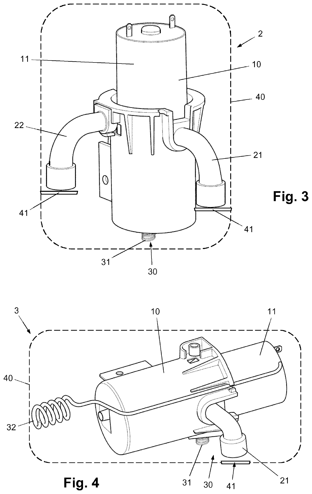
[0024]The invention is in the field of pump devices, particularly pump devices comprising a housing in which the actual pump is accommodated, and comprising at least one conduit that is connected to the pump and that is configured to enable transport of fluid to and / or from the pump.

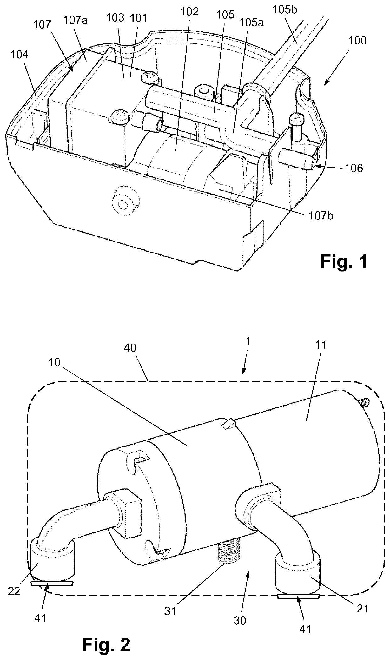
[0025]In FIG. 1, a conventional pump device 100 is shown, in order to address some general aspects of a pump device, and also to provide insight in some disadvantageous aspects of the design according to the state of the art.

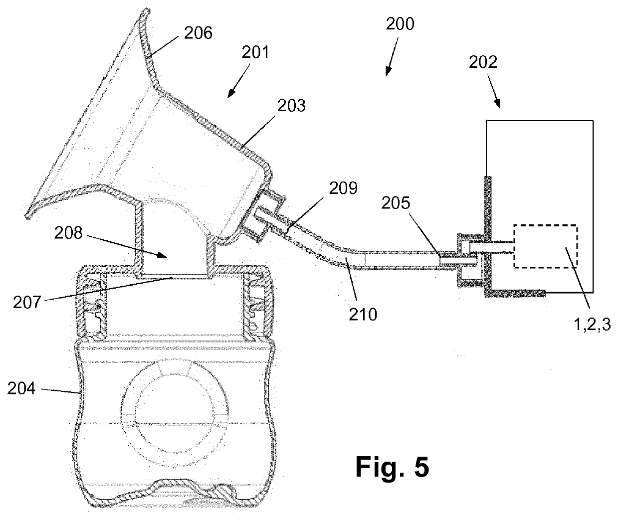
[0026]In the first place, the pump device 100 comprises a pump 101. In the shown example, the pump 101 is a micro vacuum pump that is configured to realize a vacuum cycle in a unit as may be connected to the pump 101. Hence, the pump 101 is configured to displace air, mainly to suck air from a unit as may be connected to the pump 101. Micro vacuum pumps are very well suitable to be used in consumer appliances, and a unit to be connected to the pump 101 may be a breast-receiving funne...


PUM


Abstract

A pump device (1) as may be used in a breast pump assembly comprises a pump (10) configured to put fluid in motion, a housing (40) accommodating the pump (10), at least one fluid transporting conduit (21, 22) connected to the pump (10), the at least one conduit (21, 22) extending between the pump (10) and the housing (40), thereby connecting the pump (10) to a position at the housing (40) where the housing (40) is provided with at least one opening (41) for allowing fluid to pass, and a mounting arrangement (30) for mounting the pump (10) in the housing (40). The at least one conduit (21, 22) is part of the mounting arrangement (30) and has flexible properties so as to reduce an extent to which vibrations of the pump (10) are transferred to the housing (40) through the mounting arrangement (30) during operation of the device (1).

Description

FIELD OF THE INVENTION[0001]The invention relates to a pump device, comprising a pump configured to put fluid in motion, a housing accommodating the pump, at least one conduit connected to the pump and configured to transport fluid to and / or from the pump, the at least one conduit extending between the pump and the housing, thereby connecting the pump to a position at the housing where the housing is provided with at least one opening for allowing fluid to pass, and a mounting arrangement through which the pump is mounted in the housing.[0002]The invention also relates to a breast pump assembly, comprising: (i) an expression kit including a breast-receiving funnel, a milk outlet and an air outlet, (ii) a vacuum unit for realizing a pressure cycle in the breast-receiving funnel of the expression kit, including an air inlet and a pump device as mentioned for sucking air from the breast-receiving funnel, through the air outlet of the expression kit and the air inlet of the vacuum unit,...

Claims


Application Information

Patent Timeline
Patent Type & Authority Applications(United States)
IPC IPC(8): A61M1/06
CPCA61M2205/42A61M1/064A61M2209/08A61M1/06A61M1/062F04B53/16A61M1/0697A61M1/06935A61M1/80F04B53/003
Inventor VAN ASSELDONK, JOHANNES PETRUS ANTONIUS MARIAVAN ROOIJEN, ALEXANDERAMRA, EYOB ATNAFU
Owner KONINKLJIJKE PHILIPS NV
Why Eureka
Try Eureka