Aortic-Valve Replacement Annotation Using 3D Images

a technology of aortic valves and 3d images, applied in image enhancement, instruments, applications, etc., can solve the problems of adversely affecting patient outcomes, difficult interpretation of 2d projections of 3d objects, and difficult tavr

Pending Publication Date: 2020-08-20
ECHOPIXEL
View PDF3 Cites 3 Cited by
  • Summary
  • Abstract
  • Description
  • Claims
  • Application Information

AI Technical Summary

Problems solved by technology

However, 2D projections of a 3D object (such as 2D fluoroscopy) are often difficult to interpret.
Consequently, uncertainty can be added to the aortic-valve-device sizing and the surgical plan, which can make TAVR more challenging and can adversely impact patient outcomes.

Method used


Image

  • Aortic-Valve Replacement Annotation Using 3D Images
  • Aortic-Valve Replacement Annotation Using 3D Images
  • Aortic-Valve Replacement Annotation Using 3D Images

Examples


Embodiment Construction

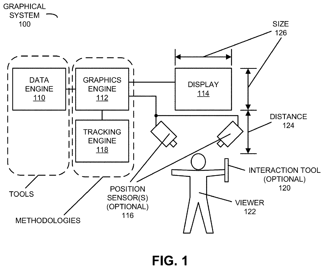
[0047]Human perception of information about the surrounding environment contained in visible light (which is sometimes referred to as ‘eyesight,’‘sight,’ or ‘vision’) is facilitated by multiple physiological components in the human visual system, including senses that provide sensory inputs and the cognitive interpretation of the sensory inputs by the brain. The graphical system in the present application provides rendered images that intuitively facilitate accurate human perception of 3D visual information (i.e., the awareness of an object or a scene through physical sensation of the 3D visual information). Notably, the graphical system in the present application provides so-called True 3D via rendered left-eye and right-eye images that include apparent image parallax (i.e., a difference in the position of the object or the scene depicted in the rendered left-eye and the right-eye images that approximates the difference that would occur if the object or the scene were viewed along ...


PUM


Abstract

A computer that determines at least an anatomic feature associated with an aortic valve is described. During operation, the computer generates a 3D image associated with an individual's heart. This 3D image may present a view along a perpendicular direction to a 2D plane in which bases of a noncoronary cusp, a right coronary cusp and a left coronary cusp reside. Then, the computer may receive information specifying a set of reference locations that are associated with an aortic-root structure. Next, the computer automatically determines, based, at least in part, on the set of reference locations, at least the anatomical feature, which is associated with an aortic valve of the individual and a size of an aortic-valve device used in a transcatheter aortic-valve replacement (TAVR) procedure.

Description

CROSS REFERENCE TO RELATED APPLICATION[0001]This application claims the benefit of U.S. Provisional Application No. 62 / 805,962, entitled “Aortic-Valve-Replacement Annotation Using 3D Images,” by Anthony Chen, et al., filed Feb. 15, 2019, the contents of which are hereby incorporated by reference.[0002]This application is related to: U.S. patent application Ser. No. ______, “Glasses-Free Determination of Absolute Motion,” filed on Feb. 8, 2019; U.S. patent application Ser. No. 16 / 101,416, “Multi-Point Annotation Using a Haptic Plane,” filed on Aug. 11, 2018; U.S. patent application Ser. No. 16 / 101,417, “Multi-Point Annotation Using a Haptic Plane,” filed on Aug. 11, 2018; and U.S. patent application Ser. No. 14 / 120,519, “Image Annotation Using a Haptic Plane,” filed on May 28, 2014, the contents of each of which are herein incorporated by reference.BACKGROUNDField[0003]The described embodiments relate to computer-based techniques for annotating one or more features based at least in ...

Claims


Application Information

Patent Timeline
Patent Type & Authority Applications(United States)
IPC IPC(8): A61B34/10A61F2/24
CPCA61B2034/105A61F2/2466A61B34/10A61B2034/107A61B2034/108A61B2090/3764A61B2034/102A61B2034/2055A61B2017/00216A61B2090/368A61B2034/2065A61B2034/2048A61B2034/2051A61B2090/502A61B2090/372A61B34/20A61F2/2412A61F2/2427A61B34/25G06T7/0012G06T2207/30048
Inventor CHEN, ANTHONY GEE YOUNGZHANG, YUKASTEN, JEFFREY A.AGUIRRE-VALENCIA, SERGIO
Owner ECHOPIXEL
Why Eureka
Try Eureka