Alternative near-field gradient probe for the suppression of radio frequency interference

a near-field gradient and interference suppression technology, applied in the field of radio frequency circuits and inductive structures, can solve the problems of difficult operation in the presence of significant rfi, and difficult detection of nqr signals using near-field probes such as loop antennas, so as to achieve substantial suppression, increase the volume of usable area and/or the effect of reducing the plan footprin

Active Publication Date: 2020-08-20
LAVEDAS TOM
View PDF0 Cites 2 Cited by
  • Summary
  • Abstract
  • Description
  • Claims
  • Application Information

AI Technical Summary

Benefits of technology

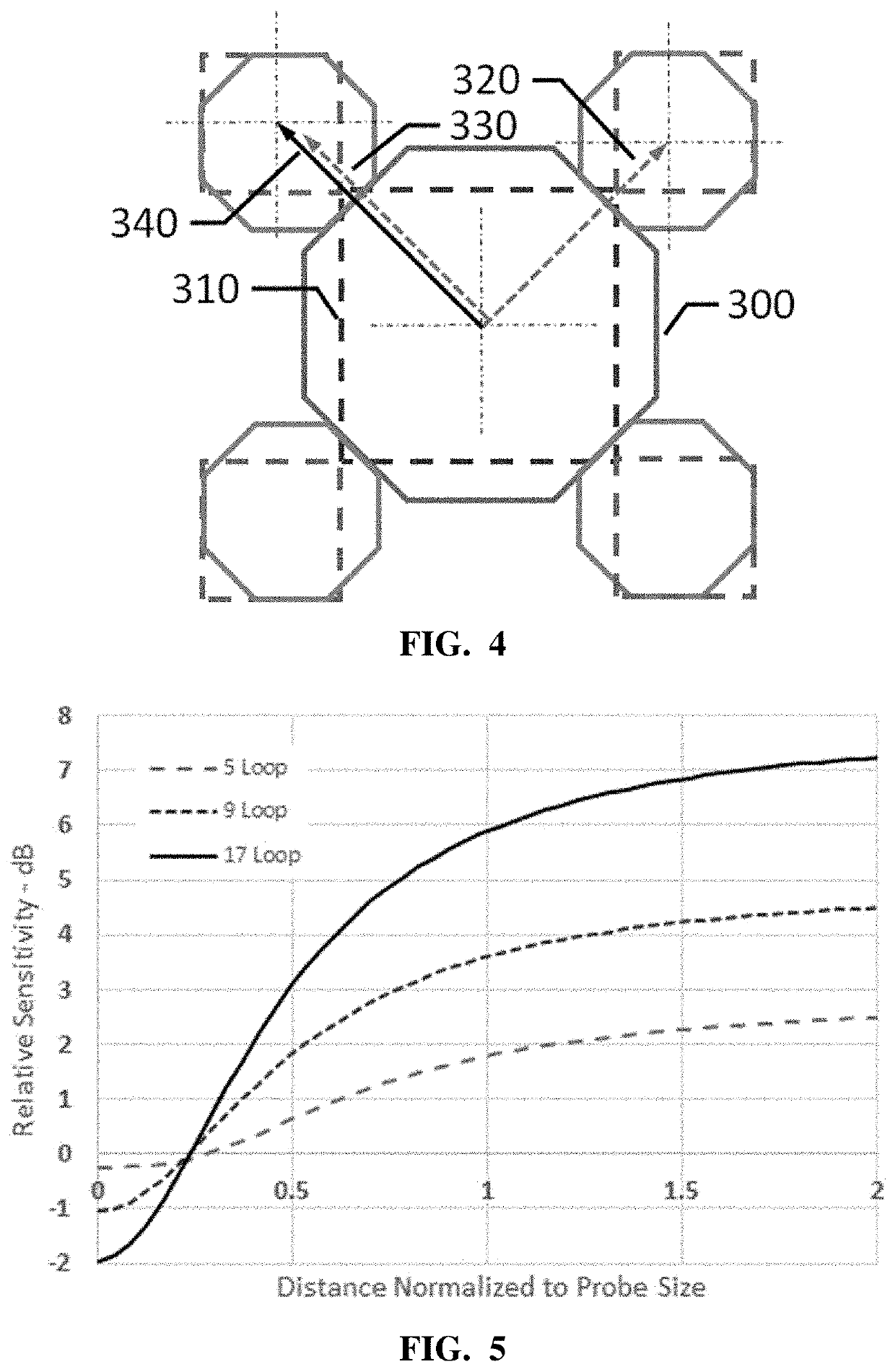
[0026]The far-field created by a current in a loop having dimensions much less than a wavelength is dependent only on its enclosed area and not its shape. And since the field pattern of such electrically small loops is fundamentally identically independent of the size or shape of the loop, the effect of this geometry is to render a net far-field that is substantially suppressed. In practice, the level of suppression is almost entirely dependent on the difference in phase delay between the centers of the central loop and the peripheral loops. That is, if the spacing is small relative to a wavelength, the suppression achieved is substantial.
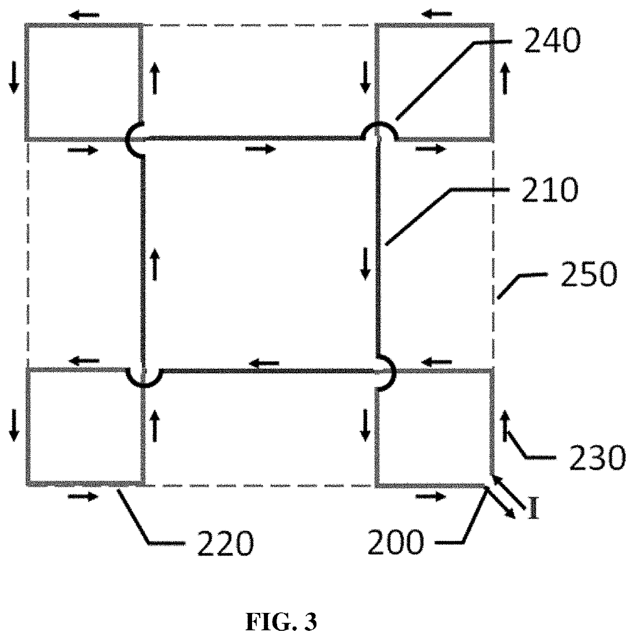
[0027]In a second implementation, twice as many smaller loops are sized to sum to the area of the larger central loop (each smaller loop having an area ⅛th of the larger loop), but rather than arrayed uniformly around the larger loop they are placed in pairs at the four corners (for a larger loop that is square-shaped) of the larger loop. That is, nine total loops where four pairs are positioned at the four corners of the central, larger loop. This approach permits use of a larger central loop, without increasing the plan footprint for the probe. The result increases the volume of usable coverage in area and / or distance from the plane of the probe. That is, it results in greater sensitivity to near-field radiation while negligibly affecting the achievable suppression of the far-field. In this embodiment, the near-field sensitivity at a given distance is greater than for a smaller central loop, while the maximum phase dispersion is only slightly worse than the five-loop configuration described above.

Problems solved by technology

One drawback with systems that use near-field probes and related technologies, especially for detection and screening of explosives, is the need to operate in the presence of significant RFI, especially far-field RFI.
Detection of NQR signals, using a near-field probe (antenna) such as a loop antenna, can be difficult in the presence of strong far-field noise sources / signals, such as AM radio transmitters, and nearby noise sources / signals, such as automobile ignitions, fluorescent lighting, computers, mobile phones, and other electronics devices.
The presence of these strong far-field noise sources / signals presents a difficulty that arises at least in part because these kinds of noise sources can create substantial coherent and non-coherent geographically distributed noise that can be within the detection frequency ranges of interest.
This kind of implementation can introduce undesirable performance compromises that can lead to performance degradation.
Additionally, the effectiveness of a remotely located sampling antenna is limited because the distributed nature of the RFI causes signals that are acquired from locations different from the location of the sensing probe to vary significantly in ways that cannot be fully compensated by adjusting the phase and amplitude of the signal derived from the sampling antenna.
Still other implementations may incorporate shielding over some or all of the probe in an attempt to reduce RFI; this is more common with larger resonant probes, and can result in bulky probe configurations.
Further, such shielding is best suited for detection of buried threats, but is much less effective in personnel screening applications.
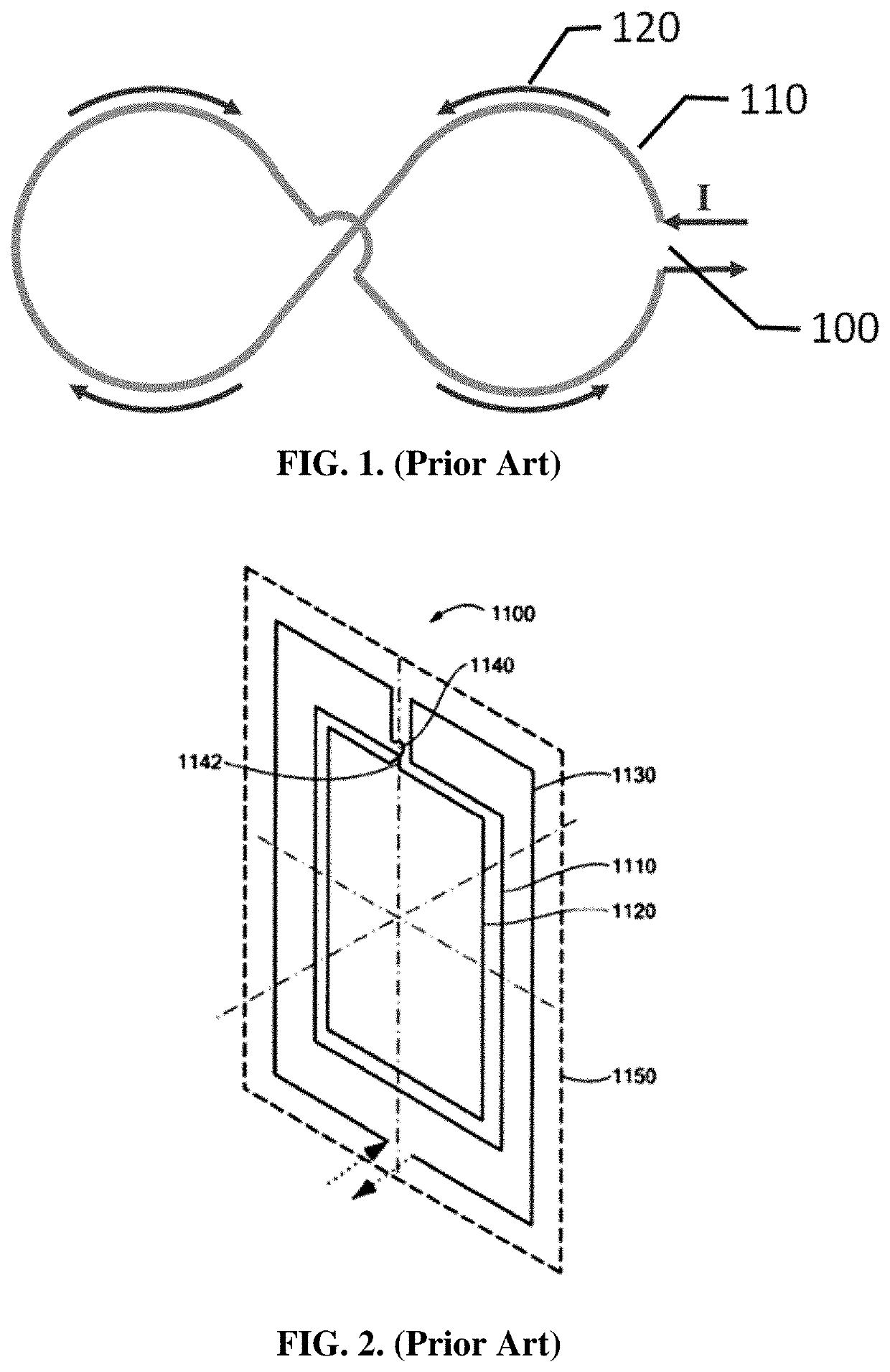
However, in this system the fields generated proximate the loops (near-field radiation) do not induce equal voltages in the various loops.
While this prior art technique offers a very significant potential to suppress the interaction with the far-field, whether suppressing generation of the far fields as part of a transmit function or suppressing reception of the far fields in a receive function, it is found to be fairly costly regarding sensitivity to signals confined to the near-field region of the probe.
That is, this technique reduces near-field sensitivity to achieve a very similar amount of far-field suppression.
Further, in practice, the extremely high suppression factors theoretically possible with such co-located geometries have been found to be limited by vagaries of the practical implementations of such systems.
However, fewer than four groups, while considered to be included as part of the scope of this invention, results in either reduced far-field suppression or offers an inferior area utilization.

Method used


Image

  • Alternative near-field gradient probe for the suppression of radio frequency interference
  • Alternative near-field gradient probe for the suppression of radio frequency interference
  • Alternative near-field gradient probe for the suppression of radio frequency interference

Examples


Embodiment Construction

[0052]A method and apparatus are described for a near-field gradient probe for suppressing radio frequency interference. In the following description, for the purposes of explanation, numerous specific details are set forth in order to provide a thorough understanding of the present invention. It will be apparent, however, to one skilled in the art that the present invention may be practiced without these specific details. In other instances, well-known structures and devices are shown in block diagram form in order to avoid unnecessarily obscuring the present invention.

[0053]Notwithstanding that the numerical ranges and parameters setting forth the broad scope are approximations, the numerical values set forth in specific non-limiting examples are reported as precisely as possible. Any numerical value, however, inherently contains certain errors necessarily resulting from the standard deviation found in their respective testing measurements at the time of this writing. Furthermore,...


PUM


Abstract

A sensor probe. The probe includes a central loop and a plurality of peripheral loops disposed peripherally relative to the central loop. To maximize far-field suppression, current flows in a first direction through the central loop and in a second direction through each one of the plurality of peripheral loops, the first direction opposite to the second direction, and current through the central loop equals current through the plurality of peripheral loops.

Description

CROSS-REFERENCE TO RELATED APPLICATIONS[0001]This application claims benefit of Provisional Appln. 62 / 771,327, filed Nov. 26, 2018, the entire contents of which are hereby incorporated by reference as if fully set forth herein, under 35 U.S.C. § 119(e).BACKGROUND1. Field of the Invention[0002]Certain of the embodiments described herein relate to RF (radio frequency) circuits, inductive structures, and related techniques and methods to improve sensitivity in remote sensing applications that suppress the reception of RF interference. This includes methods, and techniques, as well as systems, methods, and devices for improving near-field sensing applications, such as explosive detection and RFID systems (radio frequency identification systems).2. Description of the Related Art[0003]Electromagnetic waves propagating from antenna systems have near-field and far-field radiation regions. The near-field is a region near an antenna where the angular field distribution depends upon the distan...

Claims


Application Information

Patent Timeline
Patent Type & Authority Applications(United States)
IPC IPC(8): G01R29/08G01R31/315
CPCG01R29/0878G01R31/315H04B5/0081
Inventor LAVEDAS, TOM
Owner LAVEDAS TOM
Why Eureka
Try Eureka