
An orthomode transducer

a transducer and orthomode technology, applied in the field of orthomode transducers, can solve the problems of not enabling broadband performance, omts backed arrays tend to be relatively large and bulky, and beams, whatever the application, are generally undesired

Active Publication Date: 2020-08-20
SWISSTO 12 SA
View PDF0 Cites 5 Cited by
  • Summary
  • Abstract
  • Description
  • Claims
  • Application Information

AI Technical Summary

Benefits of technology

The patent text describes an orthomode transducer with beamforming capabilities that can be made in a single piece or with a few parts to reduce costs and minimize signal loss. However, the benefits of the patented solution can also be achieved by using an assembly of different parts.

Problems solved by technology

Commonly used dual-polarized waveguide-based arrays radiate through slots, thus not enabling broadband performance (>40%).
Therefore, arrays of radiating elements backed with OMTs tend to be relatively large and bulky.
These beams, whatever the application is, are generally undesired because they pollute other systems' performance.
This component is asymmetric, thus limiting the bandwidth.
Such OMTs only have one symmetry plane, thus not enabling theoretical bandwidths of up to one octave.

Method used


Image

  • An orthomode transducer
  • An orthomode transducer
  • An orthomode transducer

Examples


Embodiment Construction

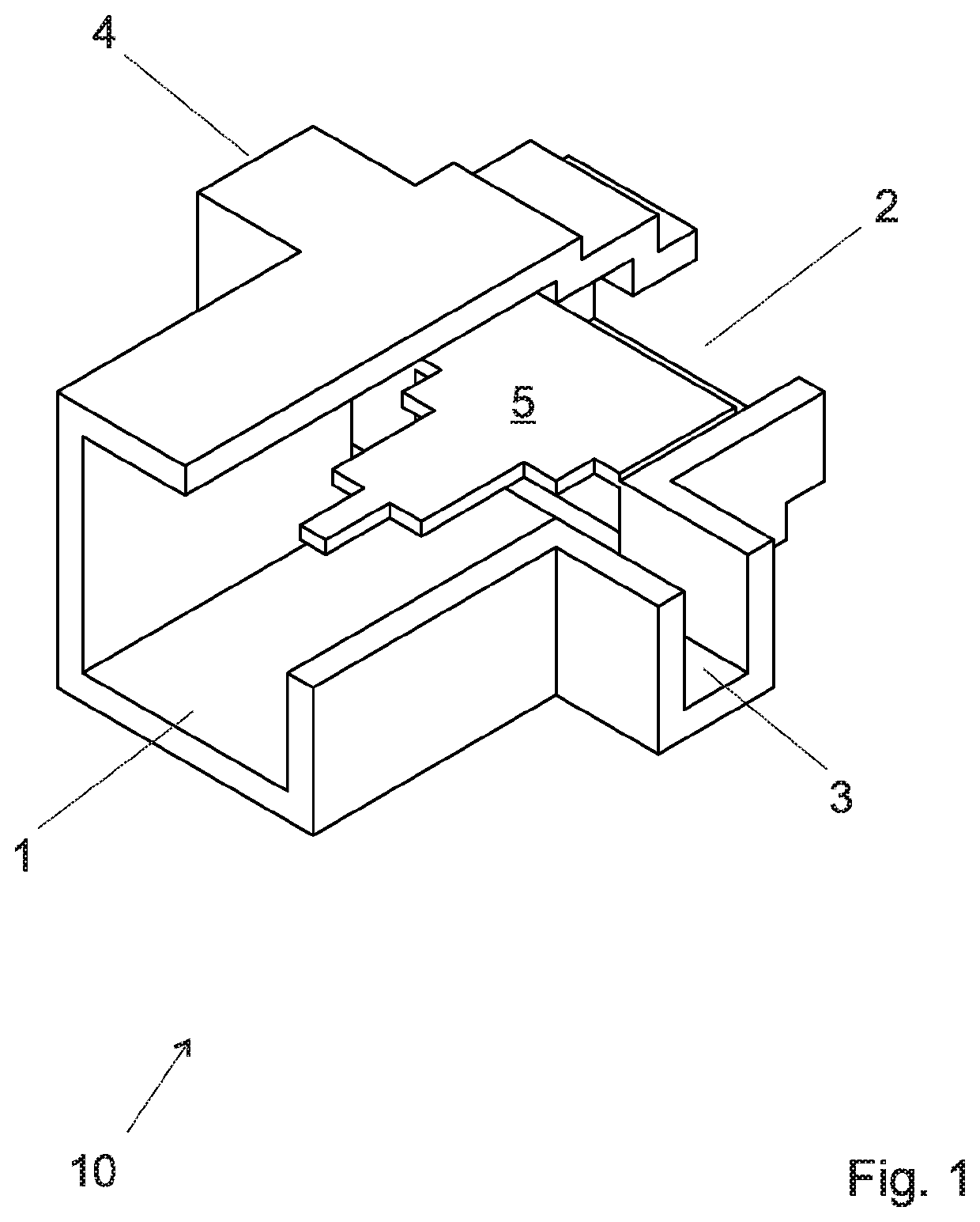
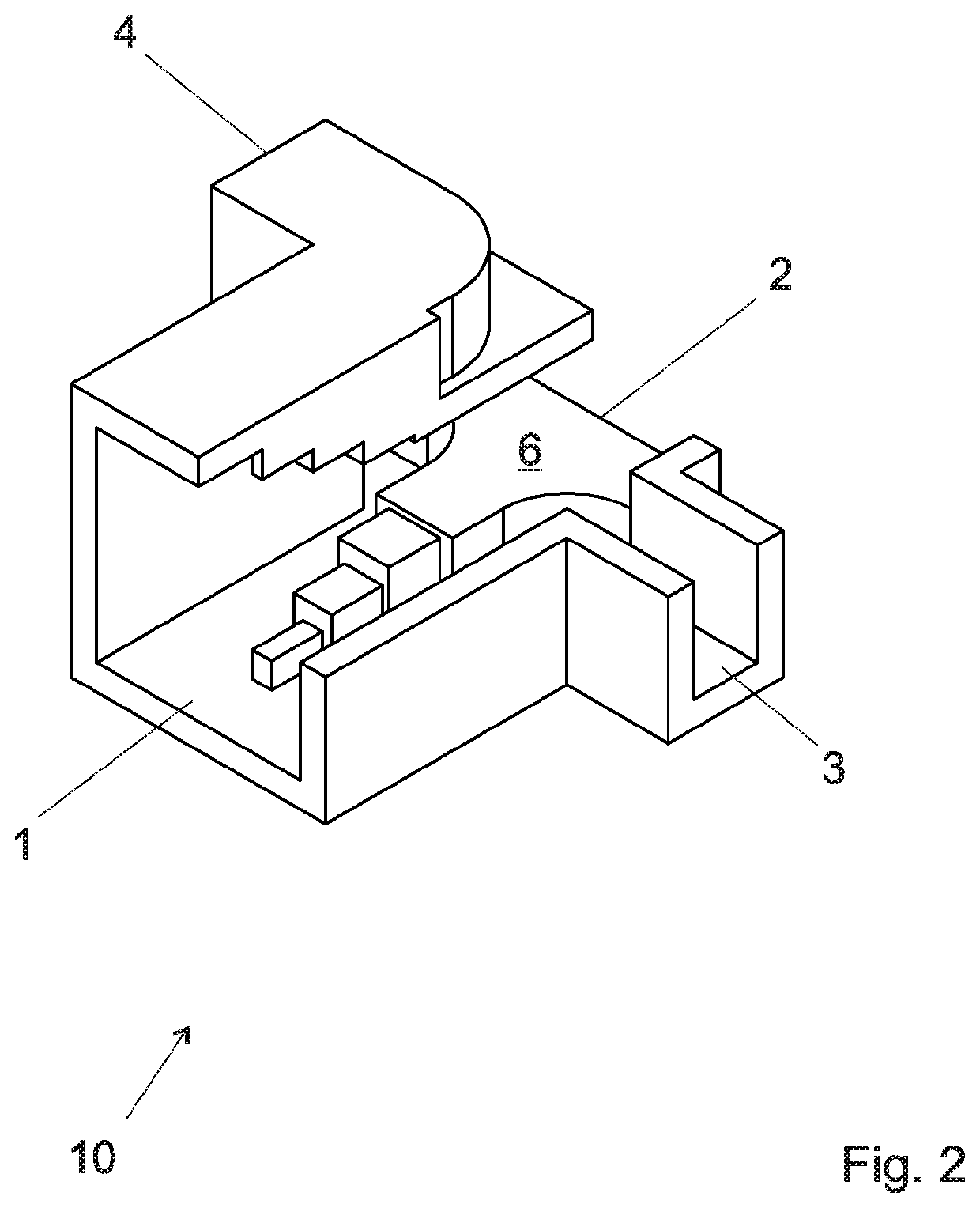
[0085]FIG. 5 shows a stack of two Boifot junctions 10 that could be used in an orthomode transducer of the invention. Those Boifot junctions could be conventional and correspond to the above described junctions of FIG. 1 or 2 for example.

[0086]Each Boifot junction (FIGS. 1 and 2) 10 presents two symmetry planes: one horizontal symmetry plane (horizontal on the Figure, and parallel to the septum 5 or ridged wedge 6), and one vertical symmetry plane (vertical on the figure, and perpendicular to the septum).

[0087]Any of the illustrated Boifot junction 10 has four ports. The port 1 propagates two orthogonal polarizations (TE10-Vpol, TE01-Hpol). We will call this port the input port, although the junction is reversible and could be used in both directions, either in a receiver or in a receiver. The port 1 could have a waveguide with a rectangular section, or any other section that propagate purely degenerate modes. Symmetric geometries that propagate two modes in the desired frequency ba...


PUM


Abstract

An orthomode transducer including a first Boifot junction and a second Boifot junction. Each of the first and second Boifot junctions includes a dual polarized port, a first lateral port, a second lateral port, the first and second lateral port being single polarized, and a third single polarized port along the propagation direction of a signal in the dual polarized port. A first power divider for coupling the first lateral port of the first Boifot junction with the first lateral port of the second Boifot junction to a third port. A second power divider for coupling the second lateral port of the first Boifot junction with the second lateral port of the second Boifot junction to a third port. A third power divider for coupling the third port of the first power divider with the third port of the second power divider to a fourth single polarization port.

Description

FIELD OF THE INVENTION[0001]The present invention concerns an orthomode transducer, in particular an orthomode transducer with beamforming capabilities, and an antenna array including such a transducer.DESCRIPTION OF RELATED ART[0002]Arrays of polarized radiating elements (such as a horn antennas or waveguide apertures) are already known as a low-weight and low volume alternative to parabolic antennas. They are widely used in satellites telecommunications, radars, remote sensing or other telecommunication applications. The signal is often propagated to each element of the antenna array through waveguides or coaxial cables, or microstrip lines, or PCBs.[0003]As an example, in satellite telecommunication applications, signals can be separated or isolated from each other through the use of different signal polarizations or frequencies. As an example, two orthogonal linear polarizations of the electromagnetic waveguides can be used to provide an isolation between those signals, for inst...

Claims


Application Information

Patent Timeline
Patent Type & Authority Applications(United States)
IPC IPC(8): H01P1/161H01Q13/02H01P1/163H01P5/16
CPCH01Q13/02H01P1/161H01P5/16H01P1/163
Inventor MENARGUES GOMEZ, ESTEBANCAPDEVILA CASCANTE, SANTIAGODEBOGOVIC, TOMISLAV
Owner SWISSTO 12 SA
Learn More