Vehicle front portion structure

a front portion and vehicle technology, applied in the direction of vehicle components, superstructure subunits, instruments, etc., can solve the problems of further such as the head-up display device, and limited installation space for the in-vehicle apparatus. achieve the effect of enhancing the bending rigidity of the cowl panel and enhancing the rigidity of the vehicle body

Active Publication Date: 2020-08-27
TOYOTA JIDOSHA KK
View PDF0 Cites 2 Cited by
  • Summary
  • Abstract
  • Description
  • Claims
  • Application Information

AI Technical Summary

Benefits of technology

[0020]The vehicle front portion structure according to the first aspect has an advantageous effect that it is possible to secure an installation space for the in-vehicle apparatus while simultaneously enhancing the bending rigidity of the cowl panel.
[0021]The vehicle front portion structure according to the second aspect has an advantageous effect that the bending rigidity of the cowl panel can be further enhanced.
[0022]The vehicle front portion structure according to the third aspect has an advantageous effect that the vehicle body rigidity can be enhanced to thereby enhance the NV (noise vibration) performance.
[0023]The vehicle front portion structure according to the fourth aspect has an advantageous effect that the bending rigidity of the cowl panel can be further enhanced while securing the installation space for the head-up display device.
[0024]The vehicle front portion structure according to the fifth and seventh aspects has an advantageous effect that the pedestrian protection performance can be enhanced.
[0025]The vehicle front portion structure according to the sixth aspect has an advantageous effect that the bending rigidity of the cowl panel can be further enhanced.

Problems solved by technology

For this reason, the installation space for an in-vehicle apparatus, such as a head-up display device, is limited by the cowl panel provided inside the instrument panel.
In addition, when the reinforcing member is provided on the cowl panel for the purpose of further enhancing the rigidity of the vehicle body, the installation space for the in-vehicle apparatus is further limited.

Method used


Image

  • Vehicle front portion structure
  • Vehicle front portion structure
  • Vehicle front portion structure

Examples


Embodiment Construction

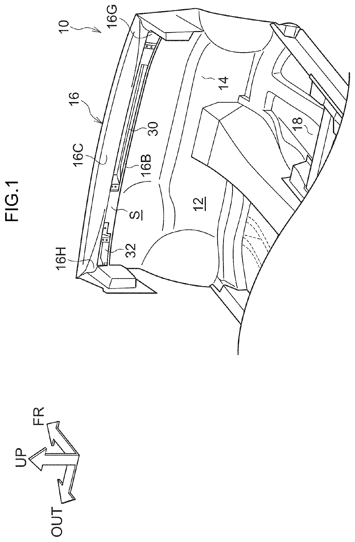
[0032]Hereinafter, an embodiment of a vehicle front portion structure according to the present disclosure will be described with reference to FIGS. 1 to 6. In each drawing, the same reference numerals are given to the same or equivalent components and parts. In addition, the dimensional ratios in the drawings are exaggerated for convenience of explanation, and may differ from actual ratios.

[0033](Overall Structure)

[0034]As shown in FIG. 1, a vehicle front portion structure 10 is applied to a cowl panel 16 provided at an upper portion of a dash panel 14 that partitions a power unit room (not shown) that constitutes a vehicle front and a vehicle compartment 12. The dash panel 14 is made of sheet metal and is disposed with the plate thickness direction being substantially the vehicle front-rear direction. The lower end portion of the dash panel 14 is joined to the front end portion of the floor panel 18, and the floor panel 18 constitutes the lower surface of the vehicle compartment 12...


PUM


Abstract

A pair of reinforcing members that extend along the extending direction of the cowl panel and that face each other in the vehicle width direction are attached to the cowl panel, and the pair of reinforcing members in the cowl panel are attached to the cowl panel. A head-up display device is provided at a position corresponding to between the two. That is, since the head-up display device can also act as a reinforcing member, the reinforcing structure is continuously provided in the extending direction of the cowl panel. Therefore, the bending rigidity of the cowl panel can be enhanced. Thereby, securing of the installation space of a head-up display apparatus and the enhanced of the bending rigidity of a cowl panel can be made compatible.

Description

CROSS-REFERENCE TO RELATED APPLICATION[0001]This application is based on and claims priority under 35 USC 119 from Japanese Patent Application No. 2019-033236 filed on Feb. 26, 2019, the disclosure of which is incorporated by reference herein.BACKGROUNDTechnical Field[0002]The present disclosure relates to a vehicle front portion structure.Related Art[0003]Japanese Patent Application Laid-Open (JP-A) No. 7-309254 discloses an invention relating to a cowl structure of a vehicle. In this cowl structure, a cowl panel is coupled to an upper end portion of a dash panel that is provided inside the instrument panel and divides a vehicle compartment and a vehicle front portion of the vehicle. The cowl panel has a cowl bottom surface extending in the vehicle width direction, and the cowl bottom surface functions as a beam so that the bending rigidity of the cowl panel with respect to the load acting along the vehicle width direction is enhanced.[0004]In recent years, the number of vehicles a...

Claims


Application Information

Patent Timeline
Patent Type & Authority Applications(United States)
IPC IPC(8): B62D25/08G02B27/01B60K35/00
CPCB60K35/00B62D25/081B60K2370/1529G02B27/0149B62D25/08
Inventor ISHIOKA, HIROTAKAMINEI, TAICHI
Owner TOYOTA JIDOSHA KK
Why Eureka
Try Eureka