Shield terminal and shield connector

a shield connector and shield terminal technology, applied in the direction of coupling contact members, coupling device connections, two-part coupling devices, etc., can solve the problems of insufficient shielding properties of inner conductor terminals, and achieve the effect of improving mounting reliability, good shielding properties, and less likely to deform

Active Publication Date: 2020-08-27
SUMITOMO WIRING SYST LTD
View PDF0 Cites 5 Cited by
  • Summary
  • Abstract
  • Description
  • Claims
  • Application Information

AI Technical Summary

Benefits of technology

[0008]A shield connector may include the above-described shield terminal with a dielectric between the inner conductor terminal and the outer conductor terminal. The shield connector also may include a connector housing for accommodating the shield terminal. The shield achieves a good shielding property, and the shield connector can be used suitably, for example, as a shield connector for high-speed communication of an automotive vehicle.
[0009]The connector housing may include a recess recessed in a direction retracted from a position where the third outer conductor connecting piece is connected to the ground portion of the circuit board. According to this configuration, it is possible to avoid contact of the connector housing with solder paste applied at the position where the third outer conductor connecting piece is connected to the ground portion of the circuit board and to improve mounting reliability on the circuit board. Further, the recess makes the connector housing less likely to deform and helps to ensure coplanarity with the circuit board.

Problems solved by technology

Thus, the shielding property of the inner conductor terminal may not be sufficient.

Method used


Image

  • Shield terminal and shield connector
  • Shield terminal and shield connector
  • Shield terminal and shield connector

Examples


Embodiment Construction

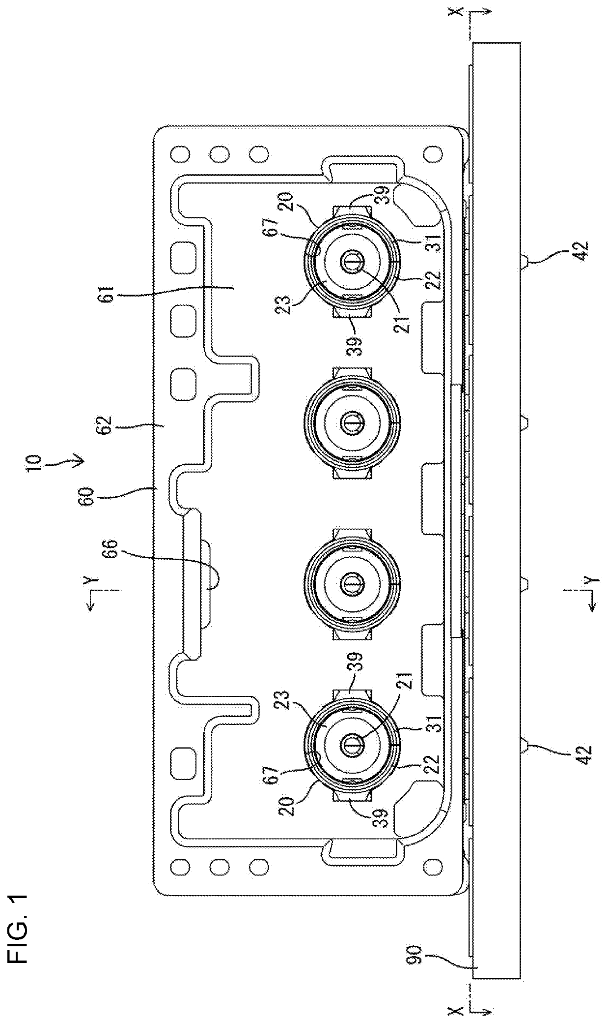
[0018]An embodiment of the invention is described with reference to FIGS. 1 to 8. A shield connector 10 of this embodiment is installed in an unillustrated automotive vehicle and is used in high-speed communication between in-vehicle electrical components. Note that, in the following description, a left side of FIG. 4 is referred to as a front concerning a front-rear direction and upper and lower sides are based on a vertical direction of FIGS. 1 and 4.

[0019]As shown in FIGS. 1 and 4, the shield connector 10 includes shield terminals 20 and a connector housing 60 for accommodating the shield terminals 20. The shield terminal 20 includes an inner conductor terminal 21, an outer conductor terminal 22 surrounding the outer periphery of the inner conductor terminal 21 and a dielectric 23 interposed between the outer conductor terminal 22 and the inner conductor terminal 21.

[0020]The inner conductor terminal 21 is formed, such as by bending a conductive metal plate. As shown in FIG. 4, t...


PUM


Abstract

A shield terminal (20) includes an inner conductor terminal (21) and an outer conductor terminal (22) surrounding the inner conductor terminal (21). The outer conductor terminal (21) has a pull-out opening (46) through which an inner conductor connecting piece (26) of the inner conductor terminal (21) is pulled toward a circuit board (90). The outer conductor terminal (22) includes outer conductor connecting pieces that face the pull-out opening (46) and that include first and second outer conductor connecting pieces (53, 54) located on both sides across the inner conductor connecting piece (26) in a plan view and a third outer conductor connecting piece (42) that faces the inner conductor connecting piece (26) in a direction orthogonal to an arrangement direction of the first and second outer conductor connecting pieces (53, 54) at a position between the first and second outer conductor connecting pieces (53, 54) in the arrangement direction.

Description

BACKGROUNDField of the Invention[0001]The invention relates to a shield terminal and a shield connector.Related Art[0002]Japanese Unexamined Patent Publication No. 2008-192474 discloses a shield terminal including an inner conductor terminal, an outer conductor terminal surrounding the inner conductor terminal and a dielectric interposed between the outer conductor terminal and the inner conductor terminal. The shield terminal is accommodated into a connector housing. The inner conductor terminal is a tab-like structure bent into an L shape and includes a board mounting tab extending in a vertical direction. The board mounting tab of the inner conductor terminal is inserted into a through hole of a circuit board. The outer conductor terminal is composed of an outer conductor terminal body covering the inner conductor terminal and a lid body for closing an opening on a back surface of the outer conductor terminal body. The outer conductor terminal body includes board mounting tabs pr...

Claims


Application Information

Patent Timeline
Patent Type & Authority Applications(United States)
IPC IPC(8): H01R13/6582H01R13/502H01R13/10H01R13/6587H01R13/6593
CPCH01R13/10H01R13/6593H01R13/502H01R13/6582H01R13/6587H01R13/648H01R12/724H01R13/6594H01R24/50H01R2103/00
Inventor HASHIMOTO, NORIHITOMITSUI, SHOHEIKANG, LIPINGKUBOTA, MOTOKIKASUGA, MASANOBUYAMANAKA, WATARUKANEMURA, KEISUKEHIRANO, AIWAKAHARA, SHINOBU
Owner SUMITOMO WIRING SYST LTD
Why Eureka
Try Eureka