Robotic optical navigational surgical system

Pending Publication Date: 2020-09-03
US PATENT INNOVATIONS LLC
View PDF2 Cites 4 Cited by
  • Summary
  • Abstract
  • Description
  • Claims
  • Application Information

AI Technical Summary

Benefits of technology

[0008]Identifying optical screening methods to locate tumors within biological tissue remains a challenge. Smart beacons targeting cancer tumors are being developed at an increasingly rapid pace. Bio-Imaging techniques in combination with surgery have improved because of the identi

Problems solved by technology

Identifying optical screening methods to locate tu

Method used


Image

  • Robotic optical navigational surgical system
  • Robotic optical navigational surgical system
  • Robotic optical navigational surgical system

Examples


Embodiment Construction

[0020]The preferred embodiments of the inventions are described with reference to the drawings.

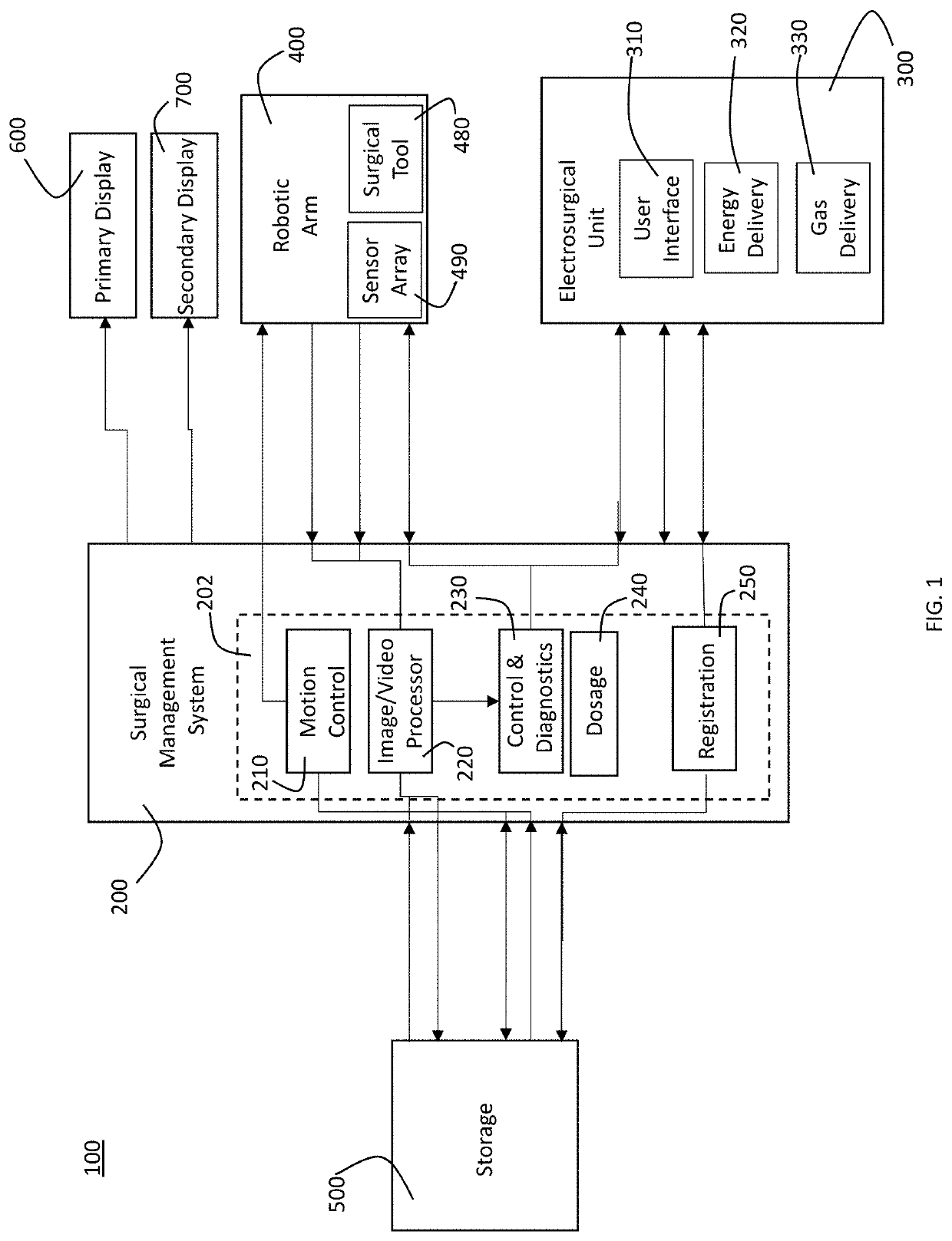
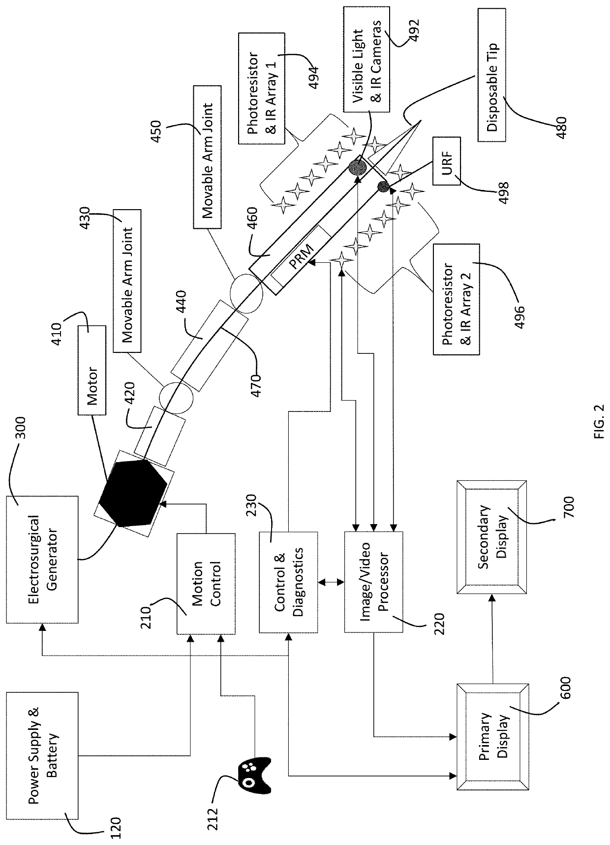
[0021]In a preferred embodiment, a robotic navigation system 100 in accordance with the present invention has a surgical management system 200, an electrosurgical unit 300, a robotic control arm 400, a storage 500, a primary display 600 and a secondary display 700. A disposable tip or tool 480 and a sensor array or camera unit 490 are mounted on or incorporated into the robotic control arm 400. The electrosurgical unit 300 provides for a variety of types of electrosurgery, including cold atmospheric plasma, argon plasma coagulation, hybrid plasma cut, and other conventional types of electrosurgery. As such, the electrosurgical unit provides both electrical energy and gas flow to support the various types of electrosurgery. The electrosurgical unit preferably is a combination unit that controls deliver of both electrical energy and gas flow, but alternatively may a plurality of units such t...


PUM


Abstract

An automated robotic navigational surgical system that will detect dye (which is injected external to this system) that marks the areas of operation. The color and type of dye used will be one that is both distinct and highly reflective. There are four sections to the automated robotic navigational surgical system: Energy Source, Display Unit and Control Arm, Sensor Array, Disposable Tip.

Description

CROSS-REFERENCE TO RELATED APPLICATIONS[0001]The present application claims the benefit of the filing date of U.S. Provisional Patent Application Serial No. 62 / 609,042 filed by the present inventors on Dec. 17, 2017.[0002]The aforementioned provisional patent application is hereby incorporated by reference in its entirety.STATEMENT REGARDING FEDERALLY SPONSORED RESEARCH OR DEVELOPMENT[0003]None.BACKGROUND OF THE INVENTIONField Of The Invention[0004]The present invention relates to robotic surgical systems, and more specifically to a navigation system for a robotic surgical system.Brief Description Of The Related Art[0005]A variety of minimally invasive robotic (or “telesurgical”) systems have been developed to increase surgical dexterity as well as to permit a surgeon to operate on a patient in an intuitive manner. Many of such systems are disclosed in the following U.S. patents which are each herein incorporated by reference in their respective entirety: U.S. Pat. No. 9,408,606, en...

Claims


Application Information

Patent Timeline
IPC IPC(8): A61B34/30A61B18/04
CPCA61B18/042A61B2034/107A61B2034/2057A61B34/30A61B2034/2065A61B90/361A61B2090/3612A61B90/37A61B2090/373A61B5/0071
Inventor CANADY, JEROMECANADY, CHEFFRENZHUANG, TAISENTABATABAI, DANIELWU, TSE HUAIWIGH, SHRUTIHINDS, DAVID
Owner US PATENT INNOVATIONS LLC
Why Eureka
Try Eureka