System of Interlocking Building Blocks
a technology of interlocking blocks and building blocks, applied in the field of building blocks, can solve the problems of poor suited for outdoor use or for larger constructions
- Summary
- Abstract
- Description
- Claims
- Application Information
AI Technical Summary
Benefits of technology
Problems solved by technology
Method used
Image


Examples
second embodiment
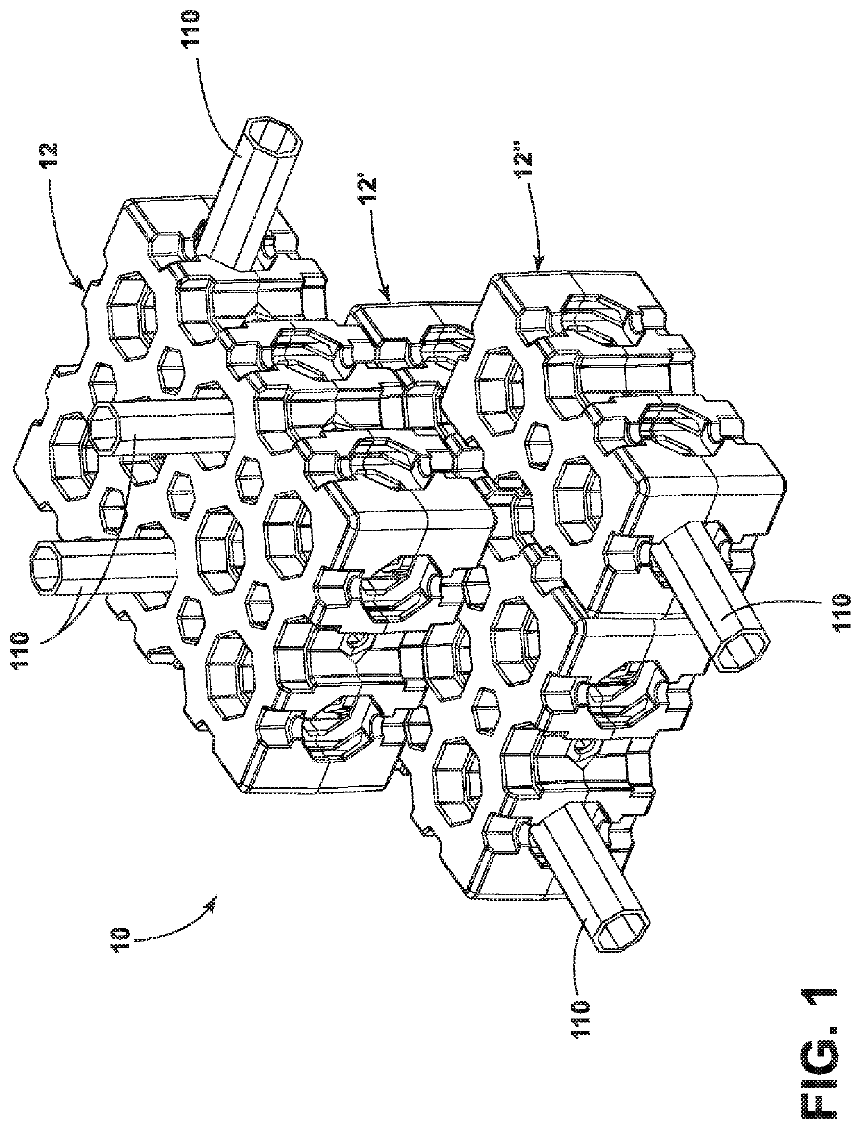
[0061] the interlocking block system 10 includes a corner block or right angle block 212, as illustrated in FIGS. 11-15. The corner block 212 is structurally and functionally similar to the block 12 of FIGS. 1-8, with like numbers corresponding to like features (e.g., socket 60 from FIGS. 1-8 is renumbered socket 260 in FIGS. 11-15), except that the walls 222, 224, 226, 228, 230, 242, 244, 246, 248 are arranged to define a v-shaped cross-section along the length of the corner block 212. That is to say, the walls 222, 224, 226, 228230, 242, 244, 246, 248 include a substantially right angle. The top outer wall 222 of the first block component 220 has a convex portion 230, and the bottom outer wall 242 of the second block component 240 has a corner portion 232. The octagonal sockets 260 are orthogonal to one another, and the hexagonal sockets 280 are orthogonal to one another. Optionally, the top outer wall 222 can be formed by two mitered walls 222a and 222b and the bottom outer wall ...
third embodiment
[0062] the interlocking block system 10 includes an elbow block or 45 degree block 312, as illustrated in FIGS. 16-20. The elbow block 312 is structurally and functionally similar to the block 12 of FIGS. 1-8, with like numbers corresponding to like features (e.g., socket 60 from FIGS. 1-8 is renumbered socket 360 in FIGS. 16-19), except that the sidewalls 322, 324, 326, 328330, 342, 344, 346, 348 include an angle. The top outer wall 322 of the first block component 320 has a convex portion 330, and the bottom outer wall 342 of the second block component 340 has an angled portion 332. The octagonal sockets 360 are arranged at an angle to one another, and the hexagonal sockets 380 are arranged at an angle to one another. Optionally, the top outer wall 322 can be formed by two mitered walls 322a and 322b and the bottom outer wall 342 can be formed by two mitered walls 342a and 342b.
fourth embodiment
[0063]It should be understood that any of the above described blocks could be provided in greater or lesser lengths and / or widths. For example, the block 12 illustrated in FIG. 2 is said to be a 2×3 block, meaning it has two lateral or outside rows of sockets 60, each row including three sockets 60. Another example shown in FIGS. 21 and 22, the block can be a 1×2 block. The block 412 of FIGS. 21 and 22 in accordance with a fourth embodiment is structurally and functionally similar to the block 12 of FIGS. 1-8, with like numbers corresponding to like features (e.g., socket 60 from FIGS. 1-8 is renumbered socket 460 in FIGS. 21-22), except that the block 412 of FIGS. 21 and 22 is a 1×2 block. Other examples include a 1×3 block, a 3×3 block, a 2×4 block, etc. Further, the corner and elbow blocks 212, 312 could be provided in greater or lesser lengths and / or widths as well, and at angles other than 90 and 45 degrees.
[0064]According to yet another embodiment, the interlocking block syste...
PUM
 Abstract
Description
Claims
Application Information