Mobile fabric water tower system

a technology of fabric water tower and water tower, which is applied in the direction of roof drainage, water supply installation, transportation and packaging, etc., can solve the problems of urban farms struggling to develop sensible and reliable irrigation systems, urban farms unable to tap into city drinking water supply, and often economic unfeasibility solutions, etc., to contaminate the local food supply produced by urban farms

Active Publication Date: 2020-09-10
RGT UNIV OF MICHIGAN
View PDF0 Cites 1 Cited by
  • Summary
  • Abstract
  • Description
  • Claims
  • Application Information

AI Technical Summary

Benefits of technology

[0040]The distribution of water is primarily gravity powered, with the option of a pump assist if necessary. Unplugged from the drip irrigation system, the host offers the ability for gardens to water plants by hand.

Problems solved by technology

In many locations, urban farms are struggling to develop sensible and reliable systems for irrigation.
Many current solutions, such as tapping into a city's drinking water supply, often prove economically unfeasible due to integrated sewage treatment and water distribution costs.
Additionally, conventional catchment surfaces, such as rooftop materials, pavements, or painted patios, when combined with the slight acidity of urban rainwater, risk contaminating the local food supply produced by urban farms.
Finally, while runoff is a threat to water quality in much of the industrialized world, the addition of agricultural waste in urban scenarios acutely exacerbates the problem.
Moreover, conventional water containment systems (including industrial cisterns, retention ponds, static sacks, and tanks) are space consuming, difficult to move, and visually deficient in the urban context.
More particularly, although it is known to use water tanks and water bladders in many residential and commercial applications, these solutions are relatively large in scale and, thus, are cumbersome to relocate even when empty and certainly immobile when full.

Method used


Image

  • Mobile fabric water tower system
  • Mobile fabric water tower system

Examples


Embodiment Construction

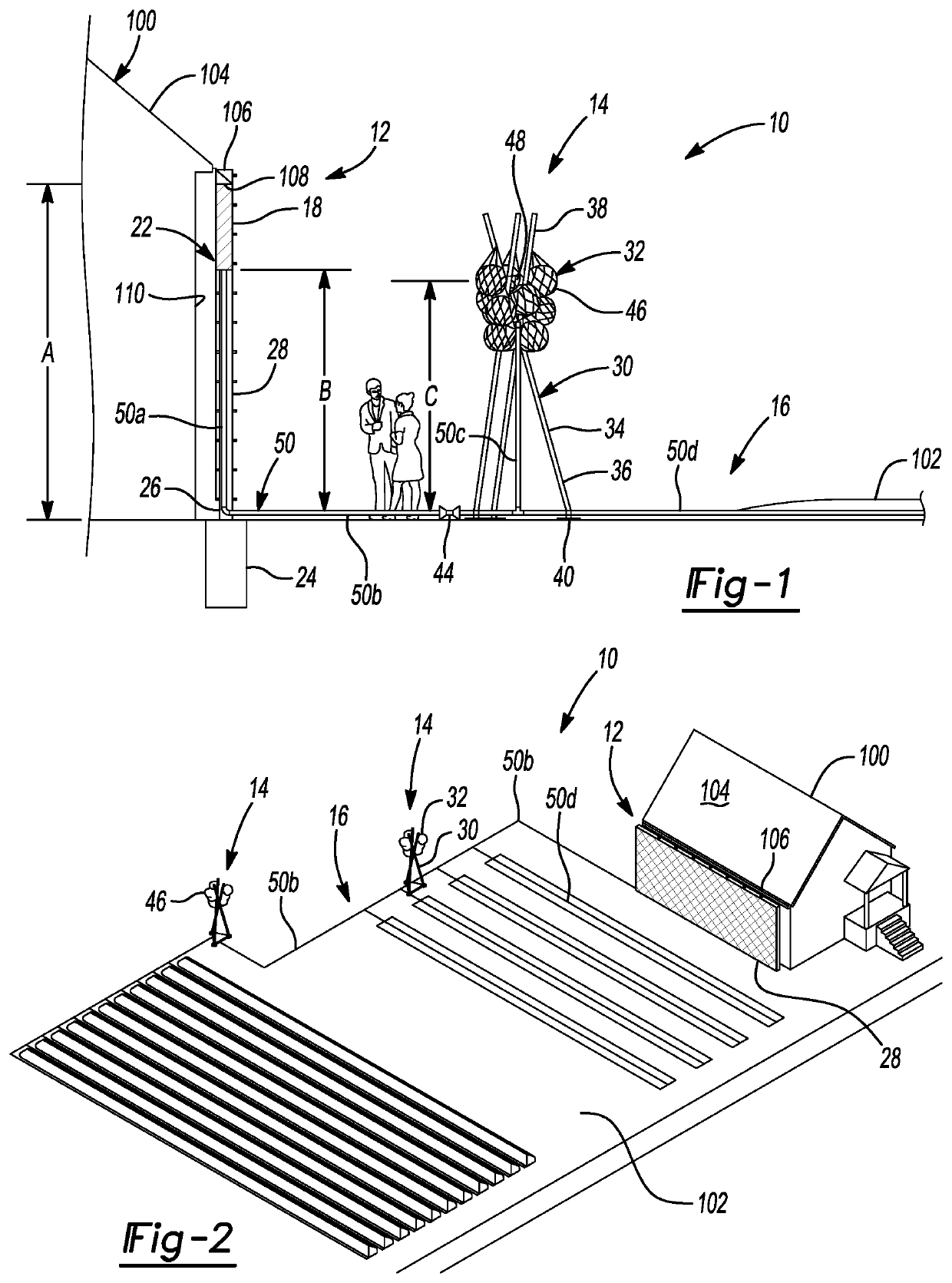
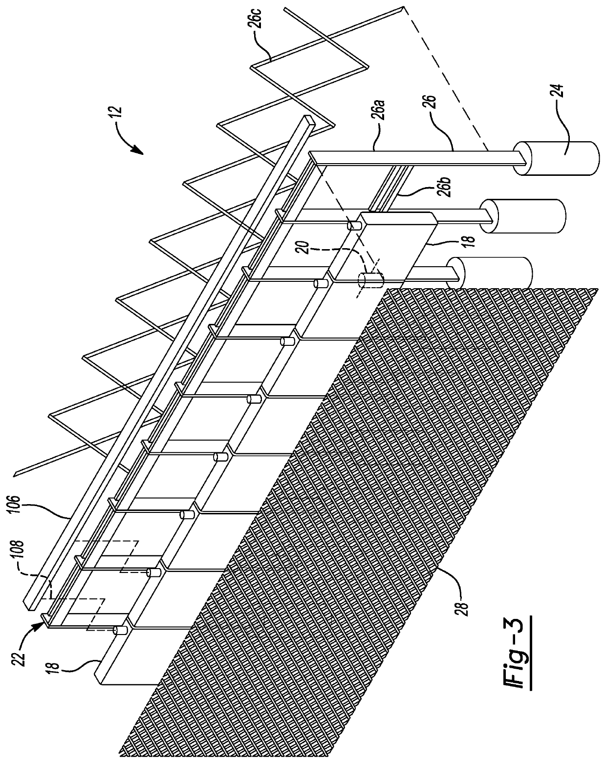
[0016]Example embodiments will now be described more fully with reference to the accompanying drawings.

[0017]Example embodiments are provided so that this disclosure will be thorough, and will fully convey the scope to those who are skilled in the art. Numerous specific details are set forth such as examples of specific components, devices, and methods, to provide a thorough understanding of embodiments of the present disclosure. It will be apparent to those skilled in the art that specific details need not be employed, that example embodiments may be embodied in many different forms and that neither should be construed to limit the scope of the disclosure. In some example embodiments, well-known processes, well-known device structures, and well-known technologies are not described in detail.

[0018]The terminology used herein is for the purpose of describing particular example embodiments only and is not intended to be limiting. As used herein, the singular forms “a,”“an,” and “the” ...


PUM


Abstract

A water tower system having a catchment system to collect climatically-produced water and route the water to an output; a water mattress system fluidly coupled below to the catchment system to collect the water from the catchment system; an elevated water tower storage system fluidly coupled to the water mattress system to receive and store water from the water mattress system, the elevated water tower storage system is located at or below the water mattress system; and a water distribution system fluidly coupled to the elevated water tower storage system to receive water from the elevated water tower storage system and distribute the water to a predetermined location.

Description

CROSS-REFERENCE TO RELATED APPLICATIONS[0001]This application claims the benefit of U.S. Provisional Application No. 62 / 559,832, filed on Sep. 18, 2017. The entire disclosure of the above application is incorporated herein by reference.FIELD[0002]The present disclosure relates to a water distribution in urban settings and, more particularly, relates to water distribution in urban settings using a mobile fabric water tower system.BACKGROUND AND SUMMARY[0003]This section provides background information related to the present disclosure which is not necessarily prior art. This section also provides a general summary of the disclosure, and is not a comprehensive disclosure of its full scope or all of its features.[0004]There are currently over 1200 urban farms and community gardens in Detroit, Mich. alone. While the practice of cultivating food and creating shared growing environments has proven critical to the wellbeing of many neighborhoods in the city, questions surrounding water man...

Claims


Application Information

Patent Timeline
Patent Type & Authority Applications(United States)
IPC IPC(8): E04D13/08E03B3/03A01G25/00E03B1/04
CPCE04D13/08E04D2013/0873E03B1/041E03B2001/047E04D2013/0893E03B3/03A01G25/00E04D13/04Y02A20/00Y02A20/108A01G9/12Y10T137/7039
Inventor SIROTA, ANYAFARGES, JEAN LOUIS M.
Owner RGT UNIV OF MICHIGAN
Why Eureka
Try Eureka