
Centrifuge and centrifugation method

a centrifugation method and centrifuge technology, applied in centrifuges, fluid controllers, membrane technology, etc., can solve the problems of inability to secure the purity of separated materials, difficulty in separating materials, so as to achieve easy separation from the substance

Active Publication Date: 2020-09-17
MEDIKAN
View PDF0 Cites 0 Cited by
  • Summary
  • Abstract
  • Description
  • Claims
  • Application Information

AI Technical Summary

Benefits of technology

The patent relates to a centrifuge and a centrifugation method that allows for easy separation of certain components from a substance through a filter. The separation is achieved by using centrifugal force to filter the certain component, and preventing it from passing through the filter even when the centrifugal force is smaller than the certain component. This makes the separation process quick and convenient. Inversely, components with smaller sizes can pass through the filter for removal by decreasing the centrifugal force. Overall, this technology allows for efficient and effective separation of components from substances.

Problems solved by technology

In general, separating the layers of the fluid by hand takes a lot of efforts, and purity of separated materials cannot be secured, and moreover, the separated materials may sometimes be lost.
To solve the aforementioned problems, a technology of mechanically separating materials having the greatest specific gravity when they are accumulated on an outer peripheral surface of a cylindrical rotary chamber during its rotation has been used, but the technology cannot be widely used.
That is, the above separation technology can be used only when a quantity of materials sought to be separated is sufficient enough to cover the entire inner wall of the cylindrical rotary chamber, and it is not easy to perform separation of the centrifuged and stacked layers according to their one-dimensional thicknesses.
In particular, the above separation method is not suitable to classify traces of cell samples.
When cells are centrifuged by a centrifuge, separated layers can be distinguished visually, but it is difficult to physically separate the layers.
When a container is slowly tilted to separate the liquid, the cells in the lowermost layer also move, and thus the separated cells may be lost due to centrifugation.
Even when the liquid separation succeeds, some cells in the uppermost layer can be lost.
Since a centrifuge used for biotechnology needs to separate cells of a human body without destruction of the cells, centrifugal force that is not sufficient to destroy the cells is applied.

Method used


Image

  • Centrifuge and centrifugation method
  • Centrifuge and centrifugation method
  • Centrifuge and centrifugation method

Examples


embodiment 1

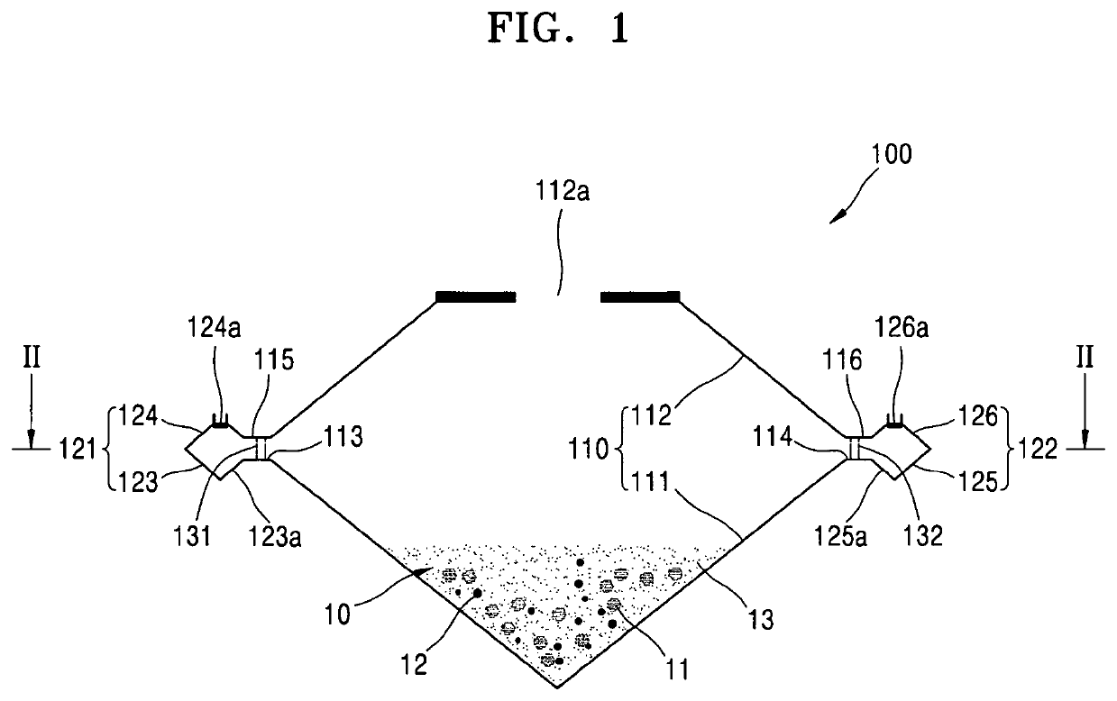
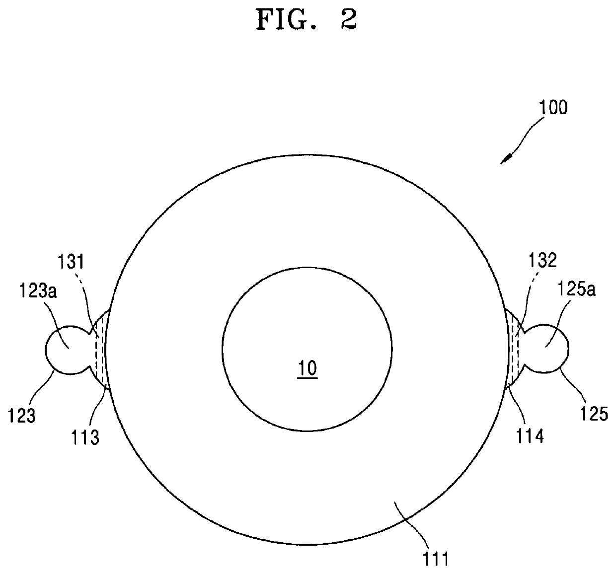
[0034]As illustrated in FIG. 1, in the present embodiment, a centrifuge 100 includes a rotary chamber 110, a first storage unit 121, a second storage unit 122, a first filter 131, and a second filter 132.

[0035]The rotary chamber 110 may contain a substance 10 therein and rotates so that centrifugal force acts on the contained substance 10. Thus, the substance 10 may be separated by components. The substance 10 contained in the rotary chamber 10 and being subject to centrifugation may be a complex fluid such as blood. In general, the complex fluid contains other components in addition to a component sought to be separated. For example, the substance 10 contained in the rotary chamber 10 and being subject to centrifugation may include: a component 11 sought to be separated; a component 12 that has a solid phase and particles having a greater mean radius than the component 11 sought to be separated; and a component 13 that has a solid or liquid phase and particles having a smaller mean...

embodiment 2

[0087]As illustrated in FIG. 10, the present embodiment relates to a centrifugation method 200. The centrifugation method 200 includes operation 210 in which a rotary chamber, which contains a substance to be centrifuged, rotates so that centrifugal force acts on the substance to be centrifuged. When the substance is injected into the rotary chamber, the substance may be injected by opening a cover of an inlet of the rotary chamber or using an injection pipe connected to the inlet.

[0088]Then, in operation 220, by passing the substance in the rotary chamber through a filter by increasing the centrifugal force according to the rotation of the rotary chamber, a certain component and a component having a smaller size than the certain component are separated from the substance in the rotary chamber and stored in a storage unit.

[0089]When the centrifugal force according to the rotation of the rotary chamber is applied, the substance in the rotary chamber moves upwards along an inclined in...


PUM

PropertyMeasurementUnit
sizeaaaaaaaaaa
sizeaaaaaaaaaa
specific gravityaaaaaaaaaa

Abstract

Provided is a centrifuge including: a rotary chamber configured to rotate so that centrifugal force acts on a substance contained in the rotary chamber; a storage unit configured to store a certain component separated from the substance in the rotary chamber by the centrifugal force according to rotation of the rotary chamber; and a filter located between the storage unit and the rotary chamber and through which the certain component, which is separated from the substance in the rotary chamber by the centrifugal force according to the rotation of the rotary chamber, passes to be stored in the storage unit. The storage unit includes a return prevention unit configured to prevent the certain component, which is separated from the substance in the rotary chamber by the centrifugal force according to the rotation of the rotary chamber and is stored in the storage unit, from returning from the storage unit to the rotary chamber. The present disclosure has an effect of easily separating a certain component sought to be separated.

Description

[0001]This application is National Stage of International Application No. PCT / KR2016 / 014362 filed Dec. 8, 2016, claiming priority from Korean Patent Application No. 10-2015-0175269 filed Dec. 9, 2015 and Korean Patent Application No. 10-2016-0166582 filed Dec. 8, 2016.TECHNICAL FIELD[0002]The present disclosure relates to a centrifuge and a centrifugation method of separating a large amount of substances, and more particularly, to a centrifuge and a centrifugation method of separating a certain substance from the large amount of substances by using centrifugal force and filters.BACKGROUND ART[0003]A centrifuge is a device for separating substances by using centrifugal force generated when an object rotates. The centrifuge may be classified according to an amount of a sample to be centrifuged, rotation speed, a rotor, and the like. A centrifuge and a centrifugation method of separating substances may be used in various fields such as the medical industry.[0004]For example, in a biote...

Claims


Application Information

Patent Timeline
Patent Type & Authority Applications(United States)
IPC IPC(8): B04B3/00B04B7/16
CPCB01D2221/10B04B7/16B01L2400/0409B04B5/0442B04B3/00B04B5/04B04B2005/0478B04B7/00
Inventor LEE, HEE YOUNGYANG, HYUN JINBAE, DAE CHANG
Owner MEDIKAN
Learn More