
Fluid Delivery Device for a Hydraulic Fracturing System

a technology of hydraulic fracturing and fluid delivery, which is applied in the directions of transportation and packaging, sealing/packing, and well accessories, etc., can solve the problems of frac pump fluid end failure, and/or relatively devastating repercussions of frac pump failure,

Active Publication Date: 2020-09-17
SPM OIL & GAS INC
View PDF0 Cites 114 Cited by
  • Summary
  • Abstract
  • Description
  • Claims
  • Application Information

AI Technical Summary

Benefits of technology

The patent describes a syringe assembly and a fluid delivery device for a hydraulic fracturing system. The syringe assembly includes a syringe with a material chamber and a base fluid chamber, and a piston that can retract and extend to push the material into the fluid conduit of the system. The fluid delivery device includes a diverter that can connect the base fluid chamber to either a base fluid reservoir or the outlet of the frac pump, depending on the pressure requirements of the system. The technical effects of the invention include improved hydraulic fracturing efficiency, simplified operation, and increased safety during the process.

Problems solved by technology

The fracking fluid often contains solid particulates and / or corrosive material such that the fracking fluid can be relatively abrasive.
Over time, the flow of the abrasive fracking fluid through the fluid end of the frac pump can erode and wear down the interior surfaces (e.g., the various internal passages, etc.) and / or the internal components (e.g., valves, seats, springs, etc.) of the fluid end, which can eventually cause the fluid end of the frac pump to fail.
Failure of the fluid end of a frac pump can have relatively devastating repercussions and / or can be relatively costly.

Method used


Image

  • Fluid Delivery Device for a Hydraulic Fracturing System
  • Fluid Delivery Device for a Hydraulic Fracturing System
  • Fluid Delivery Device for a Hydraulic Fracturing System

Examples


Embodiment Construction

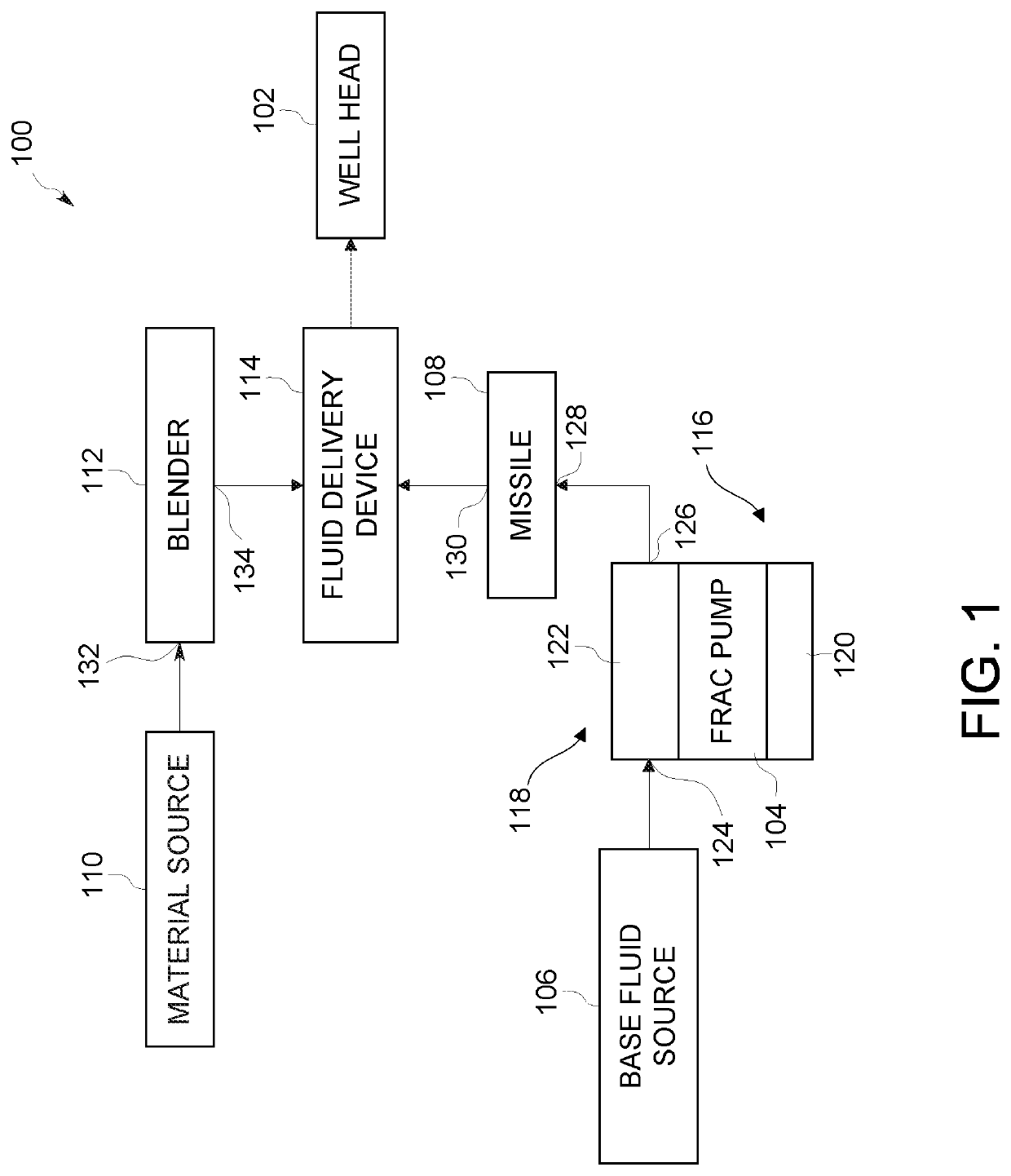
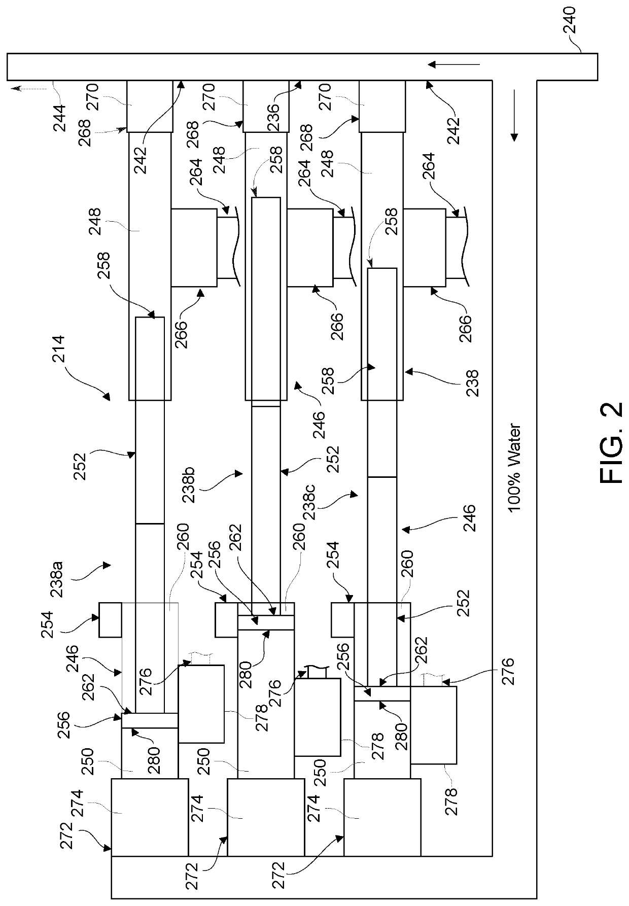
[0039]Certain embodiments of the disclosure provide a syringe assembly for a fluid delivery system that includes a syringe and a diverter that is fluidly connected to the base fluid chamber and is moveable between first and second positions. The first position of the diverter is configured to fluidly connect a base fluid chamber of the syringe to a base fluid reservoir of a hydraulic fracturing system and fluidly disconnect the base fluid chamber from an outlet of a frac pump of the hydraulic fracturing system. The second position of the diverter is configured to fluidly connect the base fluid chamber to the outlet of the frac pump and fluidly disconnect the base fluid chamber from the base fluid reservoir.

[0040]Certain embodiments of the disclosure provide a method for operating a syringe of a hydraulic fracturing system that includes fluidly connecting a base fluid chamber of the syringe with a base fluid reservoir to thereby draw at least one material of a fracking fluid into a m...


PUM

PropertyMeasurementUnit
pressureaaaaaaaaaa
corrosiveaaaaaaaaaa
period of timeaaaaaaaaaa

Abstract

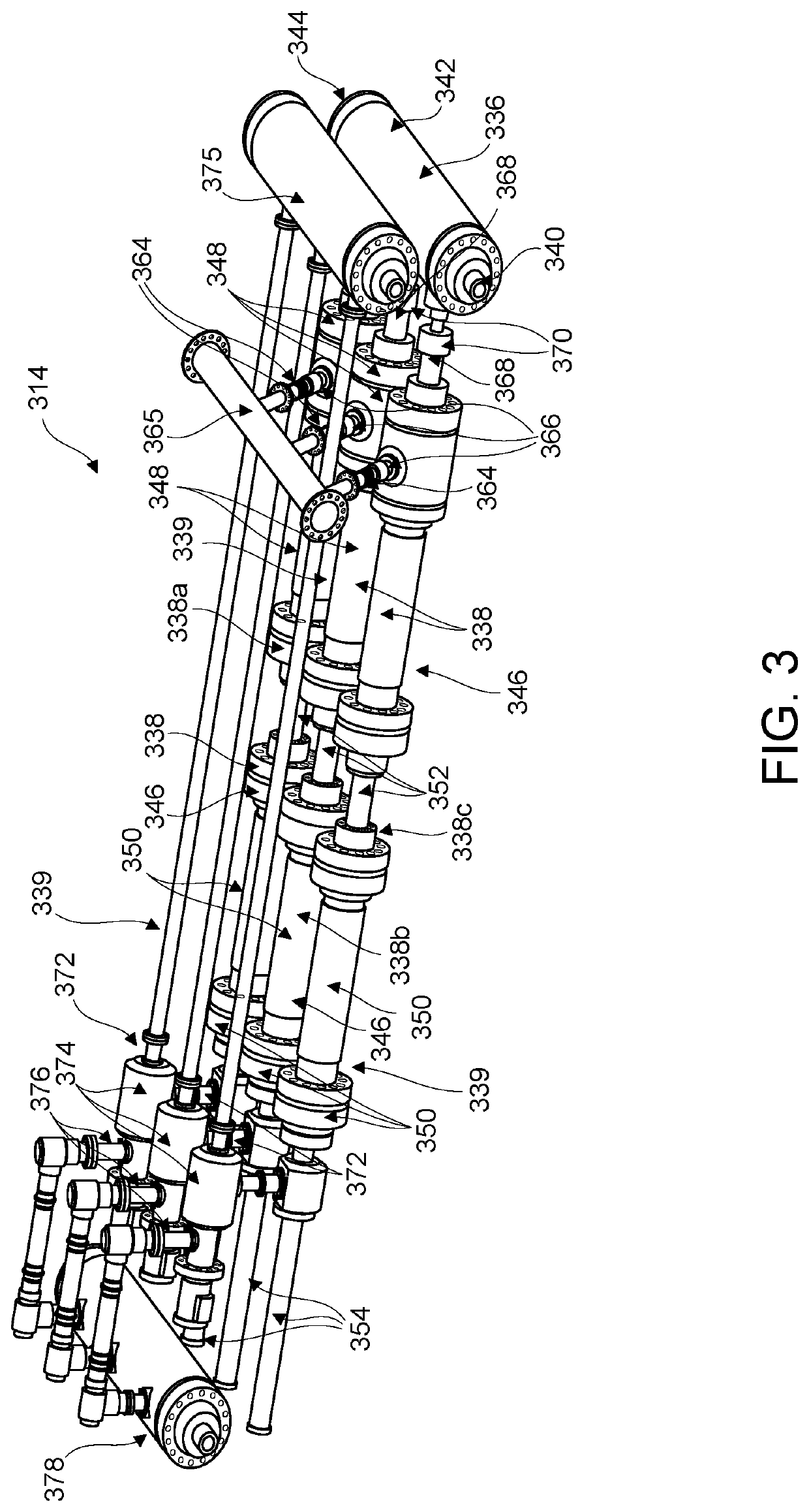
A syringe assembly for a hydraulic fracturing system includes a syringe having a material chamber, a base fluid chamber, and a piston. The material chamber is configured to be fluidly connected to a fluid conduit. The piston retracts to draw material into the material chamber. The piston extends to push the material into the fluid conduit. The syringe assembly includes a diverter fluidly connected to the base fluid chamber and moveable between first and second positions. The first position of the diverter fluidly connects the base fluid chamber to a base fluid reservoir of the hydraulic fracturing system and fluidly disconnects the base fluid chamber from an outlet of a frac pump of the hydraulic fracturing system. The second position of the diverter fluidly connects the base fluid chamber to the outlet of the frac pump and fluidly disconnects the base fluid chamber from the base fluid reservoir.

Description

CROSS-REFERENCE TO RELATED APPLICATION[0001]This Application claims priority to and the benefit of U.S. Provisional Patent Application Ser. No. 62 / 598,877 filed on Dec. 14, 2017 and entitled “SPOOL VALVE,” and PCT Patent Application Ser. No. PCT / US18 / 49144 filed on Aug. 31, 2018 and entitled “FLUID DELIVERY DEVICE FOR A HYDRAULIC FRACTURING SYSTEM,” and U.S. patent application Ser. No. 16 / 119,625 filed on Aug. 31, 2018 and entitled “FLUID DELIVERY DEVICE FOR A HYDRAULIC FRACTURING SYSTEM,” each of which are incorporated herein by reference in their entirety.TECHNICAL FIELD[0002]This disclosure relates to hydraulic fracturing systems, and in particular, to fluid delivery devices for hydraulic fracturing systems.BACKGROUND OF THE DISCLOSURE[0003]In oilfield operations, reciprocating pumps are used for different fracturing operations such as fracturing subterranean formations to drill for oil or natural gas, cementing a wellbore, or treating the wellbore and / or formation. A reciprocati...

Claims


Application Information

Patent Timeline
Patent Type & Authority Applications(United States)
IPC IPC(8): E21B21/06B01F3/08E21B43/26E21B33/038E21B33/068B01F15/04
CPCB01F15/0466B01F2215/0081E21B33/068B01F3/088E21B43/2607E21B33/038B01F3/0811E21B21/062B01F23/40B01F27/00B01F23/49B01F23/4105B01F35/88221B01F2101/49
Inventor HAIDERER, JEFFREY ROBERTSTEELE, PAUL MALCOLMLANDRUM, CONNORSKURDALSVOLD, SCOTTPOEHLS, JUSTIN LANESPENCER, GIDEON NATHANAEL
Owner SPM OIL & GAS INC
Learn More