

Light emitting apparatus and projector
- Summary
- Abstract
- Description
- Claims
- Application Information
AI Technical Summary
Benefits of technology
Problems solved by technology
Method used
Image

Examples
first embodiment
1. First Embodiment
1.1. Light Emitting Apparatus
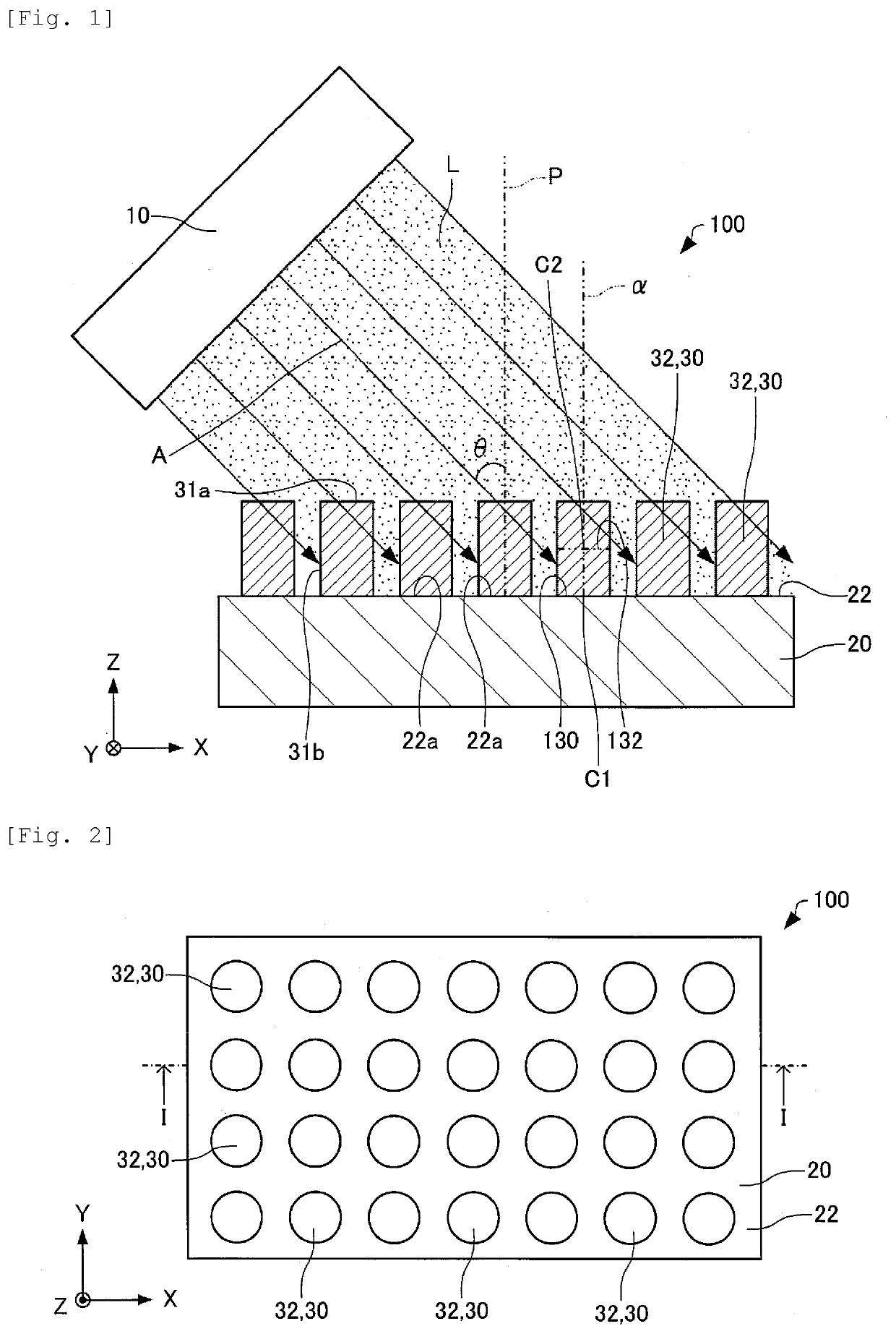
[0083]A light emitting apparatus according to a first embodiment will first be described with reference to the drawings. FIG. 1 is a cross-sectional view diagrammatically showing a light emitting apparatus 100 according to the first embodiment. FIG. 2 is a plan view diagrammatically showing the light emitting apparatus 100 according to the first embodiment. FIG. 1 is the cross-sectional view taken along the line I-I in FIG. 2. In FIGS. 1 and 2, axes X, Y, and Z are shown as three axes perpendicular to one another.
[0084]The light emitting apparatus 100 includes a light source 10, a base 20, and columnar sections 30, as shown in FIGS. 1 and 2. The light source 10 is omitted in FIG. 2 for convenience.
[0085]The light source 10 emits light L, which causes phosphors 32 in the columnar sections 30 to be excited (excitation light) . The light source 10 emits the light L obliquely with respect to a first surface 22 of the base 20. Specifically,...
second embodiment
2. Second embodiment
2.1. Light Emitting Apparatus
[0113]A light emitting apparatus according to a second embodiment will next be described with reference to the drawings. FIG. 8 is a cross-sectional view diagrammatically showing a light emitting apparatus 200 according to the second embodiment. In FIG. 8, axes X, Y, and Z are shown as three axes perpendicular to one another.
[0114]In the light emitting apparatus 200 according to the second embodiment in the following description, a member having the same function as that of a constituent member of the light emitting apparatus 100 described above has the same reference character and will not be described in detail.
[0115]In the light emitting apparatus 100 described above, the columnar sections 30 are each formed of the phosphor 32, as shown in FIG. 1. In contrast, in the light emitting apparatus 200, the columnar sections 30 each include the phosphor 32, a first semiconductor layer 34, and a second semiconductor layer 36, as shown in F...
third embodiment
3. Third Embodiment
3.1. Light Emitting Apparatus
[0161]A light emitting apparatus according to a third embodiment will next be described with reference to the drawings. FIG. 16 is a cross-sectional view diagrammatically showing a light emitting apparatus 300 according to the third embodiment. In FIG. 16, axes X, Y, and Z are shown as three axes perpendicular to one another.
[0162]In the light emitting apparatus 300 according to the third embodiment in the following description, a member having the same function as that of a constituent member of the light emitting apparatus 100 described above has the same reference character and will not be described in detail.
[0163]In the light emitting apparatus 100 described above, the columnar sections 30 are each formed of the phosphor 32, as shown in FIG. 1. In contrast, in the light emitting apparatus 300, the columnar sections 30 each include the phosphor 32 and a base section 39, as shown in FIG. 16. In the example shown in FIG. 16, the colu...
PUM
| Property | Measurement | Unit |
|---|---|---|
| Shape | aaaaa | aaaaa |
| Optical properties | aaaaa | aaaaa |
Abstract
Description
Claims
Application Information