Flexible liquid crystal display device
a liquid crystal display and flexible technology, applied in non-linear optics, instruments, optics, etc., can solve the problems of reducing the reliability or lifetime of the flexible display device, and still many technical defects to be overcome, so as to increase the reliability or lifetime of the flexible liquid crystal display device
- Summary
- Abstract
- Description
- Claims
- Application Information
AI Technical Summary
Benefits of technology
Problems solved by technology
Method used
Image
Examples
first embodiment
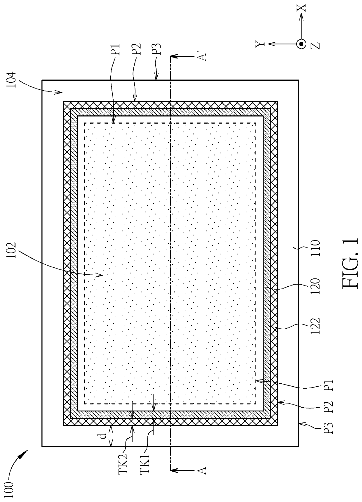
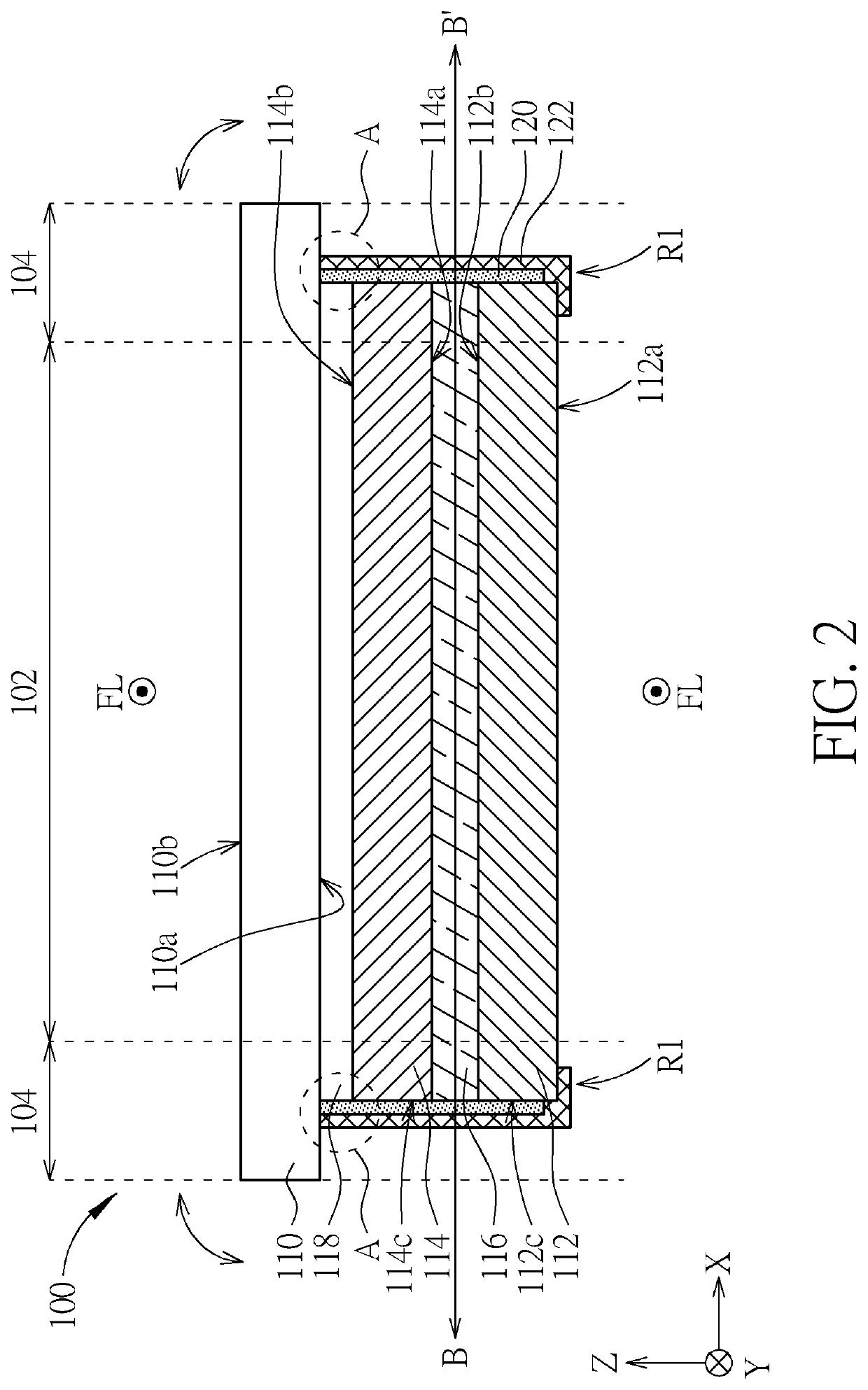
[0021]FIG. 2 is a cross-sectional view schematic diagram of a flexible liquid crystal display device according to the present disclosure, which can be a flexible liquid crystal display device that is drawn along the section line A-A′ of FIG. 1. The flexible liquid crystal display device 100 further includes a first flexible substrate 112, a second flexible substrate 114 and a liquid crystal layer 116. Wherein, the second flexible substrate 114 is disposed opposite to the first flexible substrate 112, and the liquid crystal layer 116 is disposed between the first flexible substrate 112 and the second flexible substrate 114. The cover layer 110 is disposed on the second flexible substrate 114, and the cover layer 110 has a first surface 110b facing away from the second flexible substrate 114 and a second surface 110a facing the second flexible substrate 114. The first flexible substrate 112 may include a first surface 112b and a second surface 112a opposite to each other, and the firs...
second embodiment
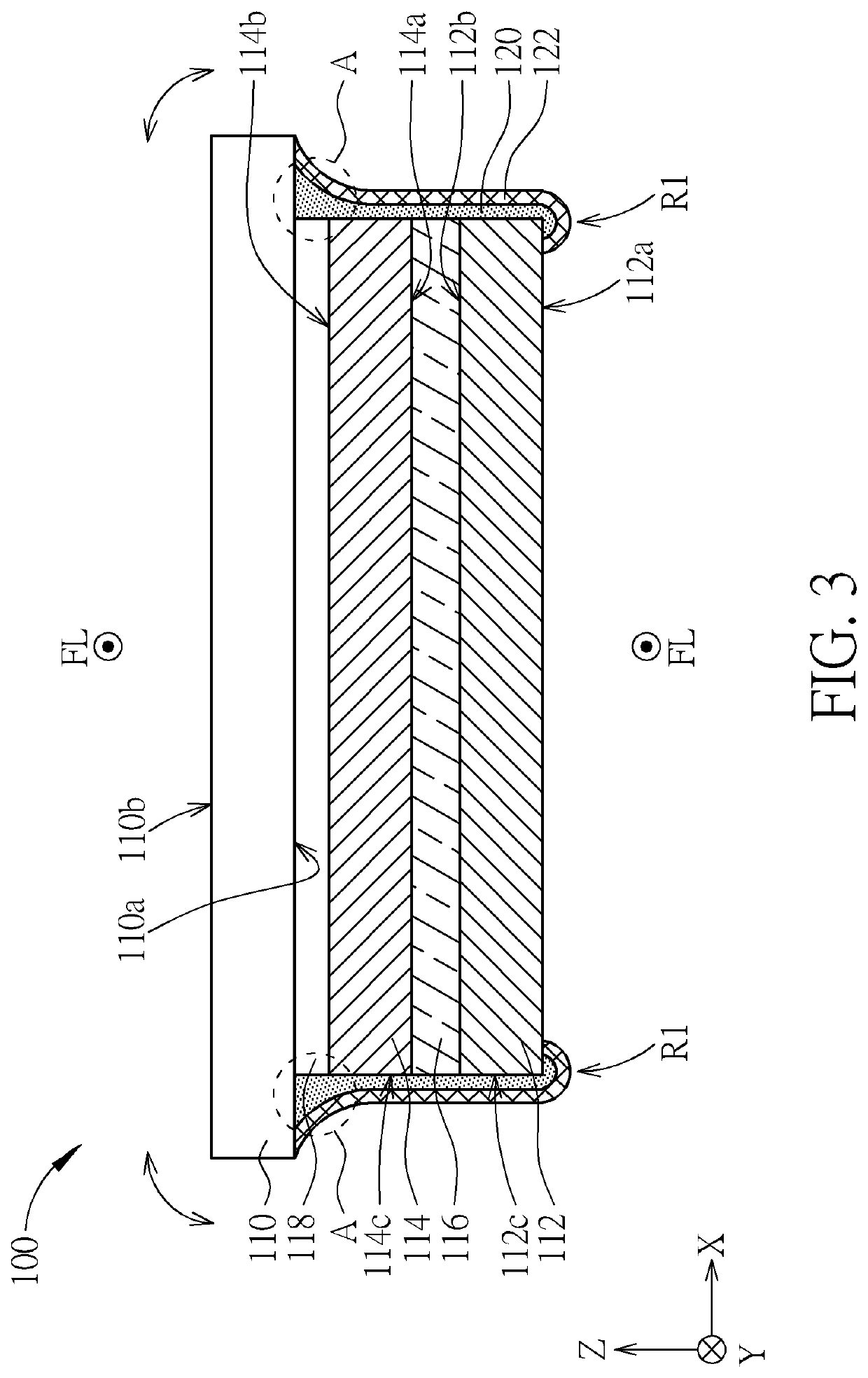
[0028]FIG. 3 is a cross-sectional view schematic diagram of a flexible liquid crystal display device according to the present disclosure. According to this embodiment, the waterproof glue 120 may be further adhered to the second surface 112a of the first flexible substrate 112. By adhering the waterproof glue 120 to the second surface 112a of the first flexible substrate 112, the moisture can be more resisted from entering the flexible liquid crystal display device 100, and therefore the risk of peeling off of the second flexible substrate 114 at the regions A or adjacent the regions A can be reduced. In this embodiment, the portions of the waterproof glue 120 and the adhesive material 122 that are adhered to the second surface 110a of the cover layer 110 have a shape of curved surface. In addition, the portions of the waterproof glue 120 and the adhesive material 122 that are adhered to the second surface 112a of the first flexible substrate 112 (that is, the bottom regions R1) hav...
third embodiment
[0029]FIG. 4 is a cross-sectional view schematic diagram of a flexible liquid crystal display device according to the present disclosure. According to this embodiment, the width of the first flexible substrate 112 in the direction X is greater than that of the second flexible substrate 114, but not limited thereto. Furthermore, the waterproof glue 120 is adhered to a portion of the first surface 112b of the first flexible substrate 112, and the adhesive material 122 is adhered to the side 112c of the first flexible substrate 112 and the second surface 112a of the first flexible substrate 112.
PUM
| Property | Measurement | Unit |
|---|---|---|
| width TK2 | aaaaa | aaaaa |
| distance | aaaaa | aaaaa |
| flexible | aaaaa | aaaaa |
Abstract
Description
Claims
Application Information
 - R&D
- Intellectual Property
- Life Sciences
- Materials
- Tech Scout
- Unparalleled Data Quality
- Higher Quality Content
- 60% Fewer Hallucinations
Browse by: Latest US Patents, China's latest patents, Technical Efficacy Thesaurus, Application Domain, Technology Topic, Popular Technical Reports.
© 2025 PatSnap. All rights reserved.Legal|Privacy policy|Modern Slavery Act Transparency Statement|Sitemap|About US| Contact US: help@patsnap.com


