Oil-lubricated kinematic module connecting system, mainly the transmission or bearing modules of industrial robot; method of kinematic module lubrication

Pending Publication Date: 2020-09-24
EROBOT J SA
View PDF5 Cites 0 Cited by
  • Summary
  • Abstract
  • Description
  • Claims
  • Application Information

AI Technical Summary

Benefits of technology

The present invention provides a system for improving the lifespan and reliability of stress-related kinematic modules in industrial robots. The system reduces oil consumption, improves lubricity performance, and increases flexibility in the connection between oil boxes. It simplifies the planning and execution of servicing operations and requires minimal operator attention. Additionally, the invention reduces environmental burden by minimizing oil consumption.

Problems solved by technology

Although the individual modules have been designed to achieve the same service-life or the same operation life according to prescribed service action, an actual load on individual axes cannot be estimated in advance when designing the robot; this load will depend on particular kinematics programmed for the particular mechanical action.
Economically usable lifetime of the robot is limited by the lifetime of the weakest unit.
Performing service tasks usually requires stopping the entire production process; sudden failure of the robot causes even more damage in production.
It is generally known that oil filtration increases the life-time of a lubricated device; but a system with a large number of components cannot be placed for each module in multiple axes of the robot.
Complicated system according to this disclosure, if used for each robot reducer, would be economically very expensive and the costs would outweigh the benefits of increased service-life.
However, such a sensor must be used for each gearbox; and even this does not solve the problem of increasing the service life-time of the oil.
Oil filtration for industrial robots is known for hydraulic power circuits which move arms and joints, such as that one of KR920005146 disclosure; however filtration of transmission oils in kinematic modules is not very usual, meaning that there is a relatively small amount of oil filler.
Lubrication and tribodiagnosis solutions are also known in the area of large rotating components, such as steam turbines; however, all such known approaches are unsuitable for robot transmission or bearing modules as the robot's technical solution cannot limit the robot's kinematic freedom or reduce its dynamic properties.
Therefore, technical solution which is simple, environmentally friendly and useful for many, preferably for all robot kinematic modules, is desirable and not known.

Method used


Image

  • Oil-lubricated kinematic module connecting system, mainly the transmission or bearing modules of industrial robot; method of kinematic module lubrication
  • Oil-lubricated kinematic module connecting system, mainly the transmission or bearing modules of industrial robot; method of kinematic module lubrication
  • Oil-lubricated kinematic module connecting system, mainly the transmission or bearing modules of industrial robot; method of kinematic module lubrication

Examples


example 1

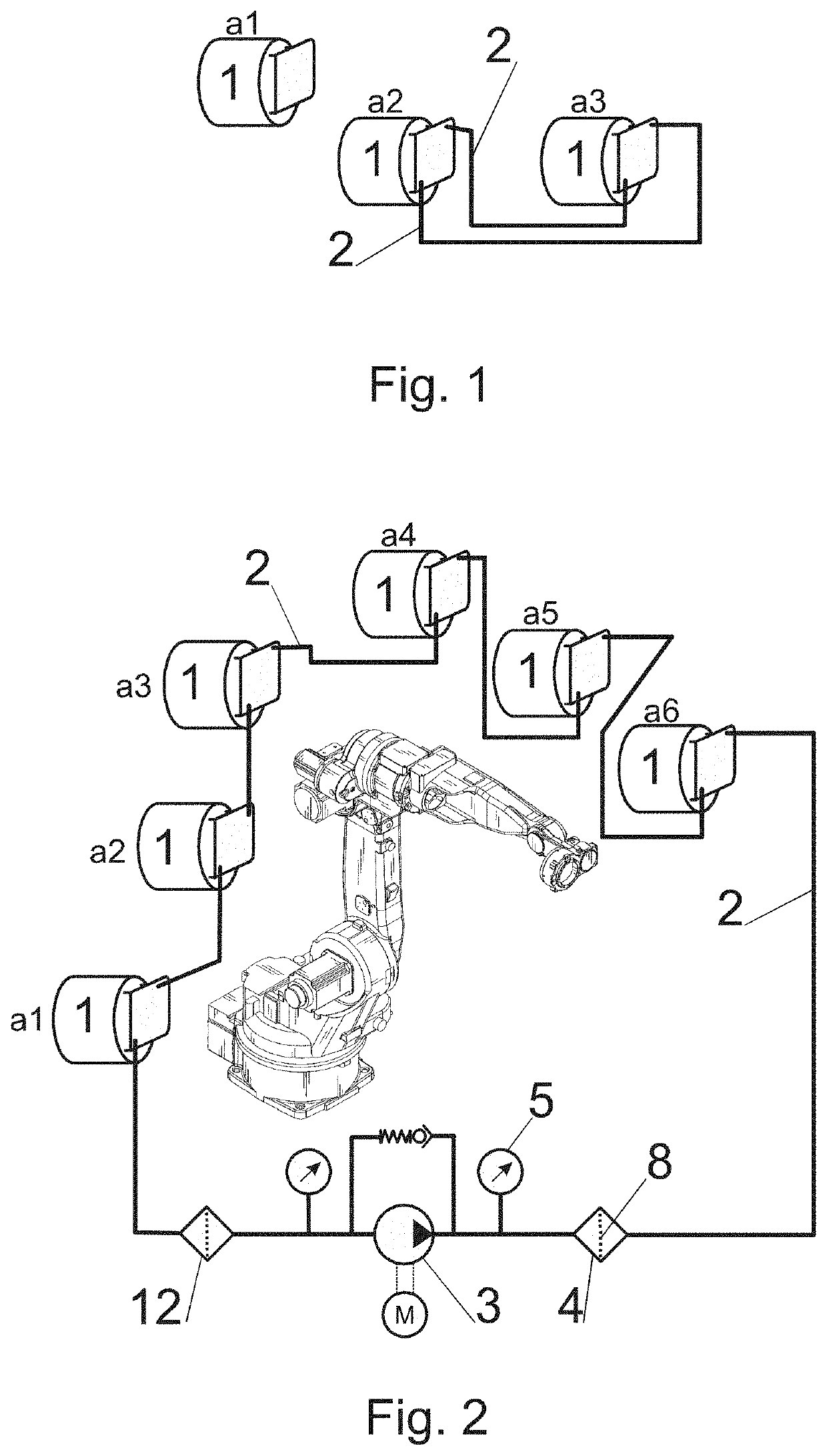
[0046]In this example and based on FIG. 1, the manipulator has four rotary joints which are mounted and moved through kinematic modules 1 in the form of bearing reducers. Three of these kinematic modules 1, rated as the most dynamically exploited, are fitted with gearboxes connected by piping and hoses. Oil circulation between the kinematic module boxes 1 is provided by movement of the planet gears of the reducers themselves; there is no need to connect the pump 3.

example 2

[0047]In this example, based on FIG. 2, the oil fillings of all six kinematic modules 1 of the industrial robot are interconnected. The connection is a simple serial-connected circulation circuit where the oil flows from the highest kinematic module 1 to the next kinematic module 1. From the last, lowest kinematic module 1, the oil is pumped through the pump 3 via the suction filter 12 and via the filtration device 4 to the highest kinematic module 1. To protect the pump 3 and its motor, the system is fitted with bypass valve and two pressure sensors connected before and after the pump 3.

[0048]The box of the lowest kinematic module 1 is being used as an oil box for the whole system. This kinematic module is designed for the largest static and dynamic load as it can carry all the adjacent arms and joints.

example 3

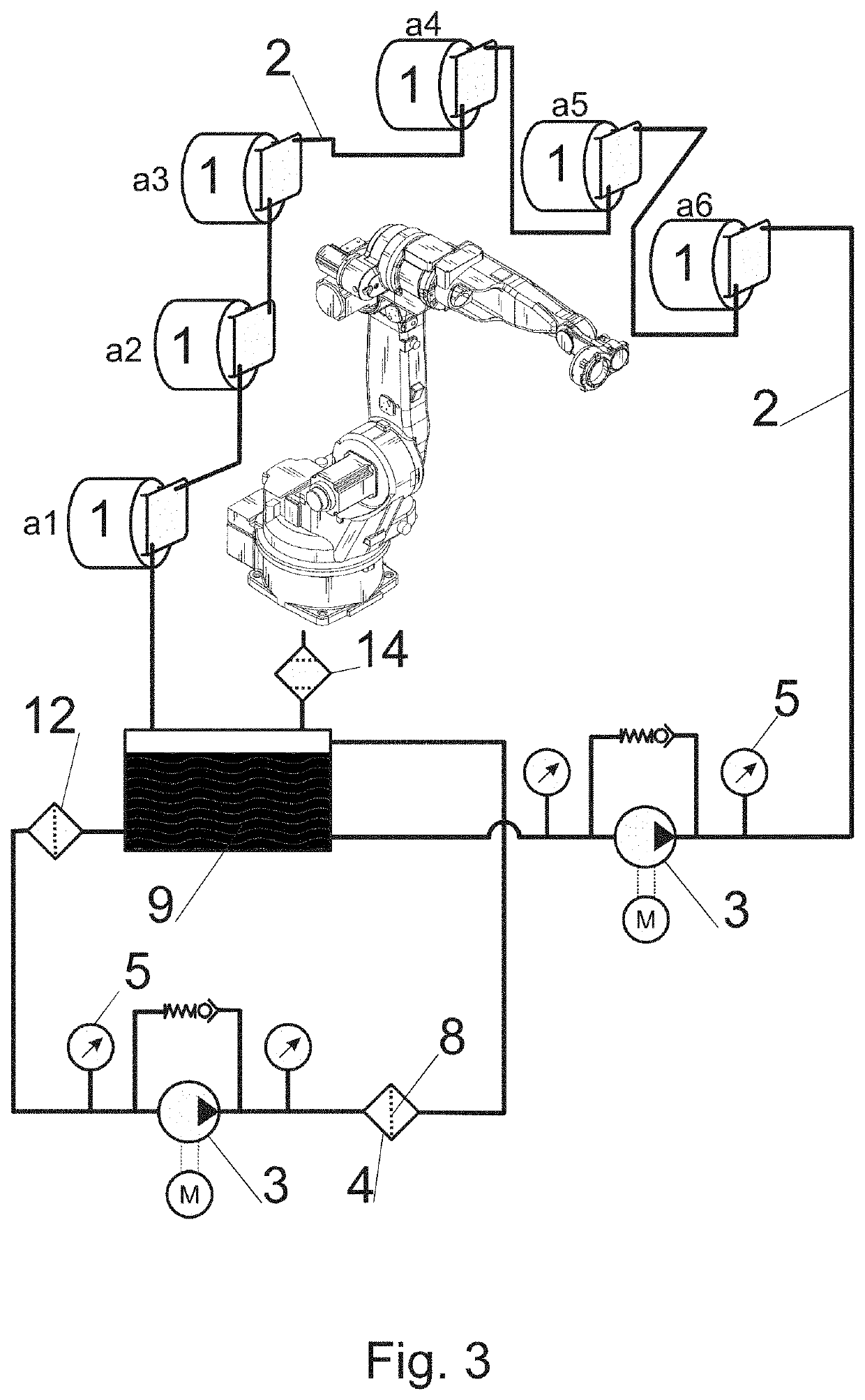
[0049]In this example, according to FIG. 3, the serial connection of the previous example is supplemented by a separate filtering circuit comprising an oil tank 9 into which the oil flows from the last kinematic module 1. Compensator of pressure changes 14 is connected to the oil reservoir 9; in this example in the form of a breathing filter. The oil reservoir 9 is connected to the branch with kinematic modules 1 by means of a pump 3; it is also connected to a filter device circuit 4 comprising a replaceable filtration element 8, pump 3 with motor, bypass valve and a pair of pressure sensors. The suction filter 12 is being used as protection against introduction of coarse impurities into the pump 3.


PUM


Abstract

The oil content of at least two kinematic modules (1) in different axes of the industrial robot is connected by the oil line (2) to the closed circuit of the oil between interconnected kinematic modules (1). In preferred arrangement, the system includes the pump (3) engaged in pushing the oil in the upper-mounted kinematic module (1) and also the filtration device (4) for filtering the oil in the circulating circuit or in a separate circuit with the oil tank (9). The system may also include at least one diagnostic element (5), for example an oil temperature sensor or an oil pressure sensor or an oil pollution sensor connected to the evaluation unit (6). The evaluation unit (6) can be interconnected with the industrial robot control system, whereby the oil economy is controlled and planned depending on the actual load of the individual kinematic modules (1). By this arrangement, you can achieve the condition in which the oil from the kinematic module (1) circulates in shared circulation with the oil from another kinematic module (1), whereas the oil gets purified through the filter device (4) by using the pump (3).

Description

CROSS REFERENCE TO RELATED APPLICATION[0001]This application is a national stage entry of PCT / 162018 / 059784 filed Dec. 7, 2018, under the International Convention claiming priority over Slovakia Patent Application No. PUV 269-2017 filed Dec. 8, 2017 and Slovakia Patent Application No. PUV 50133-2018 filed Dec. 7, 2018.FIELD OF TECHNOLOGY[0002]The invention relates to the system of module interconnection, e.g. the modules having their own oil fill to lubricate moving parts, mainly the moving parts of the transmission or bearing assemblies. Advantageously, the solution can be applied in case of industrial robots and manipulators. The invention is also aimed to the method of lubrication of kinematic modules, mainly the industrial robots.PRIOR STATE OF THE ART[0003]Robots, manipulators and similar equipments with movable joints and arms are fitted with bearing and transmission modules which provide reciprocal rotation movement of every single part of the equipment. There are also the be...

Claims


Application Information

Patent Timeline
IPC IPC(8): B25J19/00F16H57/04B25J19/02
CPCB25J19/0066B25J19/0062F16H57/0404B25J19/02
Inventor ILECKO, LUBOMIR
Owner EROBOT J SA
Why Eureka
Try Eureka