External electrical-control lamp with improved structure

a technology of external electrical control and structure, which is applied in the direction of cathode-ray/electron beam tube circuit elements, instruments, lighting and heating apparatus, etc., can solve the problems of significant influence on the reliability and stability of light-emitting diodes and other electronic components, waste of usable components, etc., to improve product reliability, improve structure, and reduce the temperature of electronic components

Inactive Publication Date: 2013-03-05
ECOLIGHTING
View PDF5 Cites 0 Cited by
  • Summary
  • Abstract
  • Description
  • Claims
  • Application Information

AI Technical Summary

Benefits of technology

[0009]In order to overcome the above-mentioned disadvantages, an external electrical-control lamp with improved structure is disclosed to provide an energy-saving operation, reduce temperature of electronic components, and increase product reliability.
[0014]In general, when the power control circuit is integrated into light-emitting diode lamp, the higher temperature, which is produced from lighting the light-emitting diodes, would decrease the lifetime and reliability of the power control circuit because of volatilization of the electrolyte solution of electrolytic capacitors thereof. Hence, the interior temperature of the light-emitting diode lamp could effectively decrease when the external power box is used.
[0015]Furthermore, a rectifying circuit installed in the light-emitting diode lamp is provided to rectified power to the light-emitting diode. Hence, interior temperature of the light-emitting diode lamp could effectively decrease because of increasing interior space of the light-emitting diode lamp (without installing other electrical control components), thus increasing the lifetime and reliability thereof.

Problems solved by technology

However, the high-temperature situation would significantly influence reliability and stability of the light-emitting diodes and other electronic components.
In addition, it is needs to discard the entire power control circuit or the light-emitting diode lamp when the power control circuit or the light-emitting diode lamp malfunctions.
This would cause waste of the usable components to raise the issues of environmental protection.

Method used


Image

  • External electrical-control lamp with improved structure
  • External electrical-control lamp with improved structure
  • External electrical-control lamp with improved structure

Examples


Embodiment Construction

[0024]Reference will now be made to the drawing figures to describe the present invention in detail.

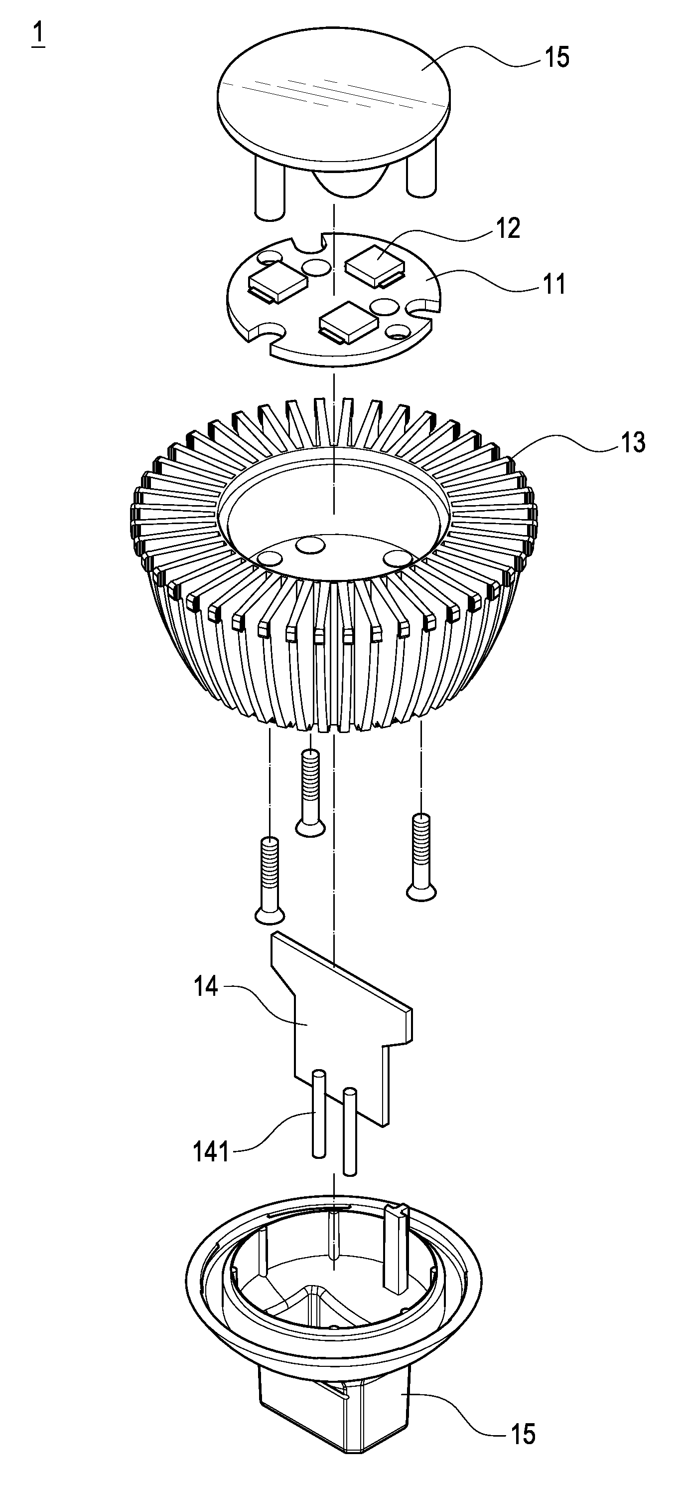
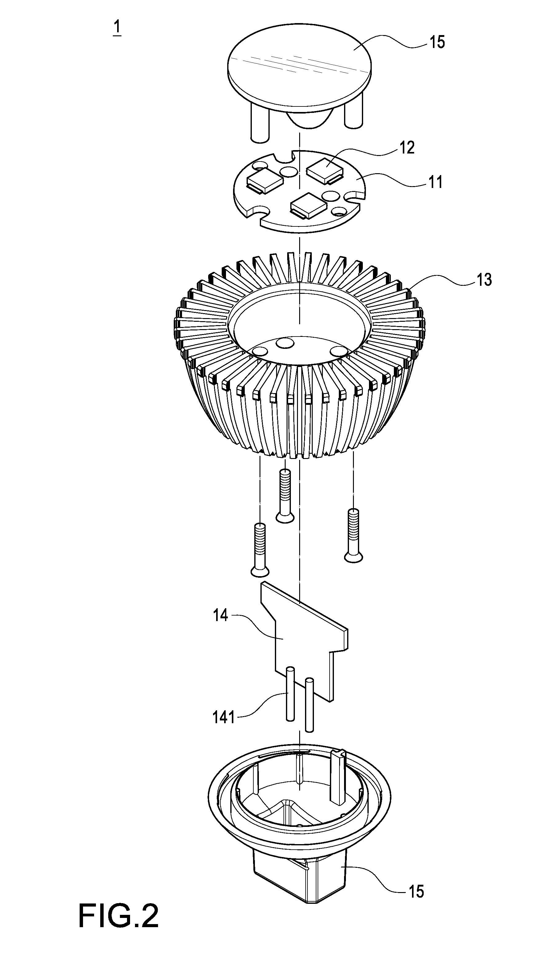
[0025]Reference is made to FIG. 1, FIG. 2, and FIG. 3 which are a perspective view, an exploded perspective view, and a block diagram of a preferred embodiment according to the present invention, respectively.

[0026]An external electrical-control lamp with improved structure includes a light-emitting diode lamp 1, an external power box 2, and a dimmer 4. The light-emitting diode lamp 1 has a circuit board 11, at least one light-emitting diode 12, a thermal module 13, a rectifying circuit 14, and a lamp housing 15. The light-emitting diode 12 is installed on the circuit board 11. The thermal module 13 provides a heat-dissipating function to the light-emitting diode 12. The rectifying circuit 14 provides a rectified power to the light-emitting diode 12. In particular, the rectifying circuit 14 is a bridge diode rectifying circuit 14. In addition, the light-emitting diode lamp 1 is held o...


PUM


Abstract

An external electrical-control lamp with improved structure includes a light-emitting diode lamp (1), an external power box (2), and a dimmer (4). The light-emitting diode lamp (1) has a circuit board (11), at least one light-emitting diode (12), a thermal module (13), and a rectifying circuit (14). The light-emitting diode (12) is installed on the circuit board (11), the thermal module (13) provides a heat-dissipating function to the light-emitting diode (12), and the rectifying circuit (14) provides a rectified power to the light-emitting diode (12). When a utility power (3) is supplied to the dimmer (4) and the external power box (2), a variable resistor of the dimmer (4) is adjusted and the utility power (3) is controlled by the external power box (2), thus adjusting the brightness of the light-emitting diode (12).

Description

BACKGROUND OF THE INVENTION[0001]1. Field of the Invention[0002]The present invention relates to a lamp structure, and more particularly to an external electrical-control lamp with improved structure that can provide an energy-saving operation, reduce temperature of electronic components, and increase product reliability.[0003]2. Description of Prior Art[0004]Early days, LEDs were used to indication or advertisement applications. With the tremendous development of science and technology, LEDs play a significant role in illumination, backlight, and display applications. Until the introduction of white LEDs, a major breakthrough in lighting applications occurs. Because LEDs present many advantages including lower energy consumption, longer lifetime, and maintenance free, the lamps of using LEDs are highly interested and popularized by world governments and companies.[0005]Today, a light-emitting diode lamp integrated into the traditional halogen lamp is developed. Hence, the conventio...

Claims


Application Information

Patent Timeline
Patent Type & Authority Patents(United States)
IPC IPC(8): H05B37/00H05B44/00
CPCF21K9/137F21V23/04H05B33/0803F21Y2101/02F21V29/773F21K9/233F21Y2115/10H05B45/31H05B45/345H05B45/355
Inventor CHUANG, SHIH-JENTSAI, CHUN-YI
Owner ECOLIGHTING
Why Eureka
Try Eureka