
Plasma fill sensor

Inactive Publication Date: 2020-10-15
KONINKLJIJKE PHILIPS NV
View PDF0 Cites 0 Cited by
  • Summary
  • Abstract
  • Description
  • Claims
  • Application Information

AI Technical Summary

Benefits of technology

This patent describes a device that can determine the level of liquid in a cartridge by using a liquid level sensor that detects the reflection of light. Compared to other types of sensors, this sensor is smaller and easier to integrate into a smaller analyzer system. The device can also detect the presence of the cartridge and ensure precise positioning for accurate detection of the liquid level. Overall, this technology allows for a compact and easy-to-design analyzer system.

Problems solved by technology

However, some methods, such as capacitive sensing described in U.S. Pat. No. 6,490,920 B1, may not be suitable for a miniature system for detecting a small volume of plasma, thus resulting in relatively complex analyzing setups.
It provides a two side constraint to the cartridge, which is insufficient for accurate measurements, as the positioning of the cartridge is imperative to ensure accuracy in the measurements.
Since the prior art discussed herein provides only a two side constraints, the precise and repeated positioning is not achievable leading to error in measurements.

Method used


Image

  • Plasma fill sensor
  • Plasma fill sensor
  • Plasma fill sensor

Examples


Embodiment Construction

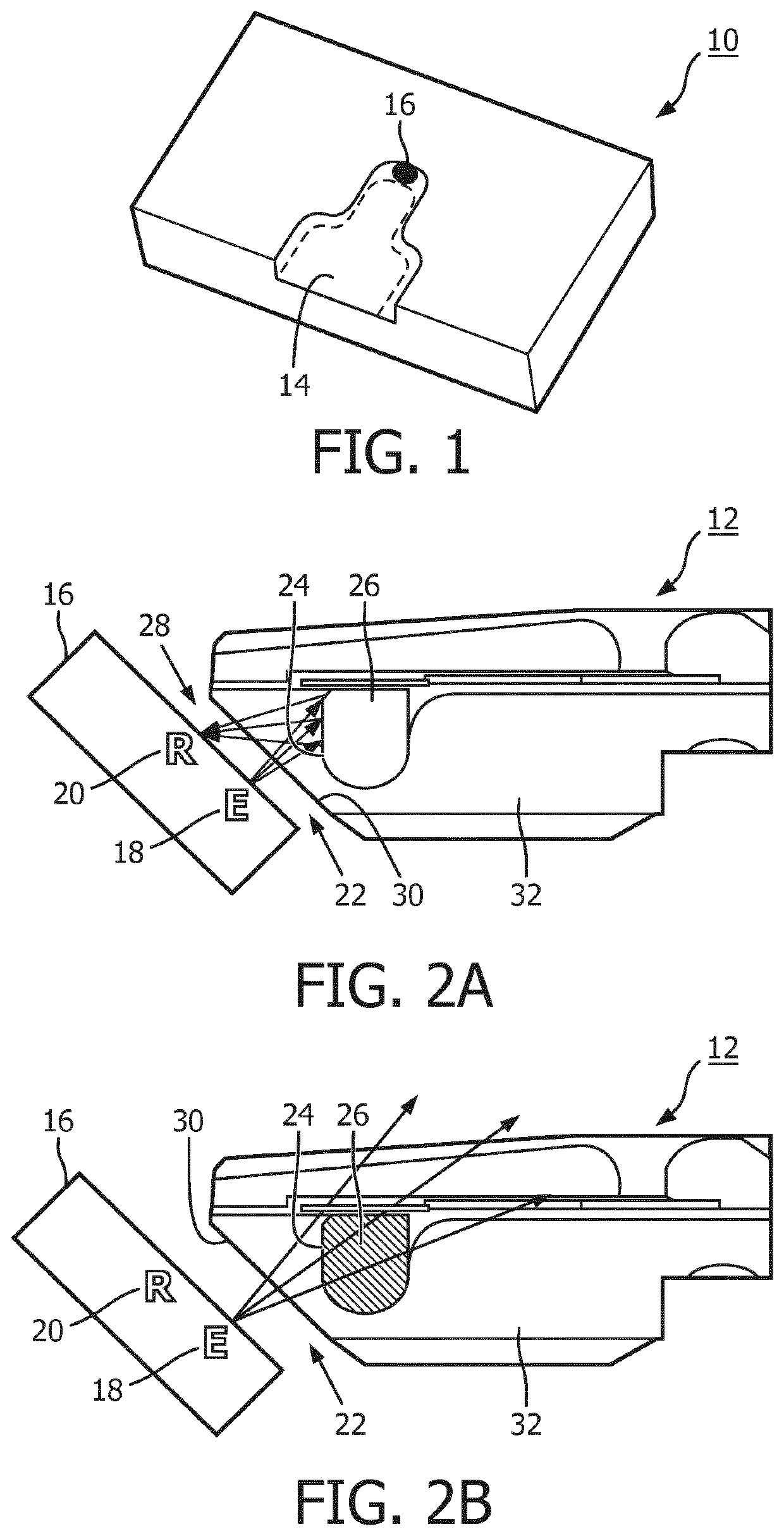
[0045]FIG. 1 shows an example of a device 10 for determining a filling level of a cartridge 12 (not shown in FIG. 1, see FIG. 2) according to an exemplary embodiment of the present invention. The device 10 comprises a cartridge interface 14 for receiving the cartridge 12 and a liquid level sensor 16.

[0046]The device 10 may also be referred to as optical engine, or optical engine unit, which relates to a unit of an analyzer system which is adapted for receiving a cartridge. The device 10 may comprise further sensors for providing certain measurements, for example, to measure the absorption of the liquid to determine e.g. the concentration of the molecule.

[0047]FIGS. 2A and 2B shows an enlarged view of the liquid level sensor 16 together with the cartridge 12 that is inserted into the cartridge interface 14 of device 10. The liquid level sensor 16 comprises a light source 18 and a light detector 20. The light source 18 is configured to provide a beam of light 22 incident upon a cavity...


PUM


Abstract

The present invention relates to blood analysis. In order to determine the filling level of a cartridge, a device (10) is provided that comprises a cartridge interface (14) for receiving a cartridge and a liquid level sensor (16). A cartridge position guiding arrangement is configured to engage with the cartridge for providing a six degree-of-freedom constraint to the cartridge. The liquid level sensor comprises a light source (18) and a light detector (20). The light source is configured to provide a beam of light (22) incident upon a cavity surface (24) of an optical pit (26) of a cartridge received by the cartridge interface. The light detector is configured to detect a portion (28) of the beam of light reflected from the cavity surface of the optical pit. The device is configured to determine a filling level of the optical pit based on the detected portion of the beam of light.

Description

FIELD OF THE INVENTION[0001]The present invention relates to the field of blood analysis, and in particular to a device for determining the filling level of a cartridge based on light reflection, to an analyzer system, and to a method for determining the filling level of a cartridge.BACKGROUND OF THE INVENTION[0002]Blood plasma separation is used in blood analysis for separating plasma from small volumes of blood e.g. in a range of 20 to 50 μl. The separated plasma, which is about 7-9 μl, fills up a cartridge, e.g. collected in an optical pit, for measuring molecule concentration. In order to ensure fool proof operation, it may be required to detect the filling of the cartridge. However, some methods, such as capacitive sensing described in U.S. Pat. No. 6,490,920 B1, may not be suitable for a miniature system for detecting a small volume of plasma, thus resulting in relatively complex analyzing setups.[0003]EP 2483080B1 discloses an ink cartridge for inkjet printers with filled-lev...

Claims


Application Information

Patent Timeline
IPC IPC(8): G01F23/292G01V8/12
CPCG01F23/292G01V8/12G01F23/2922
Inventor BHAT, RAVINDRAARPUTHA, SHASHIDHARANSUNDARAMOORYHY, RAVI BABURAIKER, ANIL SHIVRAMVAN DER LUGT, ANTHONIE
Owner KONINKLJIJKE PHILIPS NV
Learn More