
Golf Ball Tracking System

a tracking system and golf ball technology, applied in golf balls, gymnastic exercise, sport apparatus, etc., can solve the problems of lack of real-time spin and position information too costly for widespread commercial use, and lack of many aspects of current golf ball tracking systems, etc., to achieve convenient attachment or embedding, sufficient computing power, and smooth flight of the ball

Inactive Publication Date: 2020-10-22
PFC SHARED SERVICES LLC
View PDF0 Cites 8 Cited by
  • Summary
  • Abstract
  • Description
  • Claims
  • Application Information

AI Technical Summary

Benefits of technology

The present patent provides a way to easily attach or embedded a protective housing with Ultra Wideband communication and computing power into an object to be tracked, such as a golf ball. It also allows for dynamic balancing of components within the ball to ensure smooth flight. The challenge of miniaturizing circuitry for certain applications, such as golf balls, is also addressed. Overall, this technology makes it easier to track and locate objects using advanced technology.

Problems solved by technology

However, current golf ball tracking systems are lacking in many aspects in that the tracking systems do not actually track the golf ball accurately through space from impact to final resting position, nor do they provide real-time spin and position information, or are too costly for widespread commercial use.
Furthermore, many of the golf ball tracking systems cannot be used for both driving range and on-course applications.
The technology does not track the golf ball.
However, TrackMan falls short when measuring actual position after the ball lands, and providing real-time spin and positional data while in flight.
Further, TrackMan is very expensive per ball tracked and is not suited to ranges where many balls are in the air simultaneously as Trackman requires an expensive radar for each ball.
However, OnCore's ball is not expected to be USGA compliant.
However, OnCore's claims regarding the accuracy of their ball position is suspect as X, Y, Z standard GPS processing systems do not perform to 1 foot accuracy levels as the source of altitude information in not very accurate.
However, 300 yards seems too large a range for standard Bluetooth and likely requires low powered Bluetooth 5.
However, OnCore's accuracy claims and equipment requirements may be the reasons for OnCore's difficulties in production of their design.
With respect to image processing, although video sensor resolutions and frame rates are growing rapidly, they are currently still limiting factors for this application.
The lack of higher resolution means the camera lens field of view is small and hence, the number of cameras needed is large: it might just be viable for the Driving Range but isn't acceptable for the Golf Course application.
Technology advances will surely resolve some of the weaknesses of the video camera and image processing solution, but the limitations of adverse weather and imaging conditions will remain along with the challenge of finding a method of measuring ball spin without embedding sensors and electronics in the ball.
Overall, this approach does not appear viable now and does not appear to have a path to resolving the issues in the future.
This may be problematic, due principally to the difficulty of reliably pulling the reflected signal of a flying golf ball from a complex background and the unacceptable deterioration of tracking accuracy with increasing downrange distance, commercially available LIDAR systems are not, at this time, assessed as suitable as a viable and cost effective golf ball tracking system.
Therefore, there is no currently viable and cost effective golf ball tracking system for both driving range and on-course applications, which provides real-time measurements of a golf ball from the moment of impact with a golf club throughout the entirety of its travels.

Method used


Image

  • Golf Ball Tracking System
  • Golf Ball Tracking System
  • Golf Ball Tracking System

Examples


Embodiment Construction

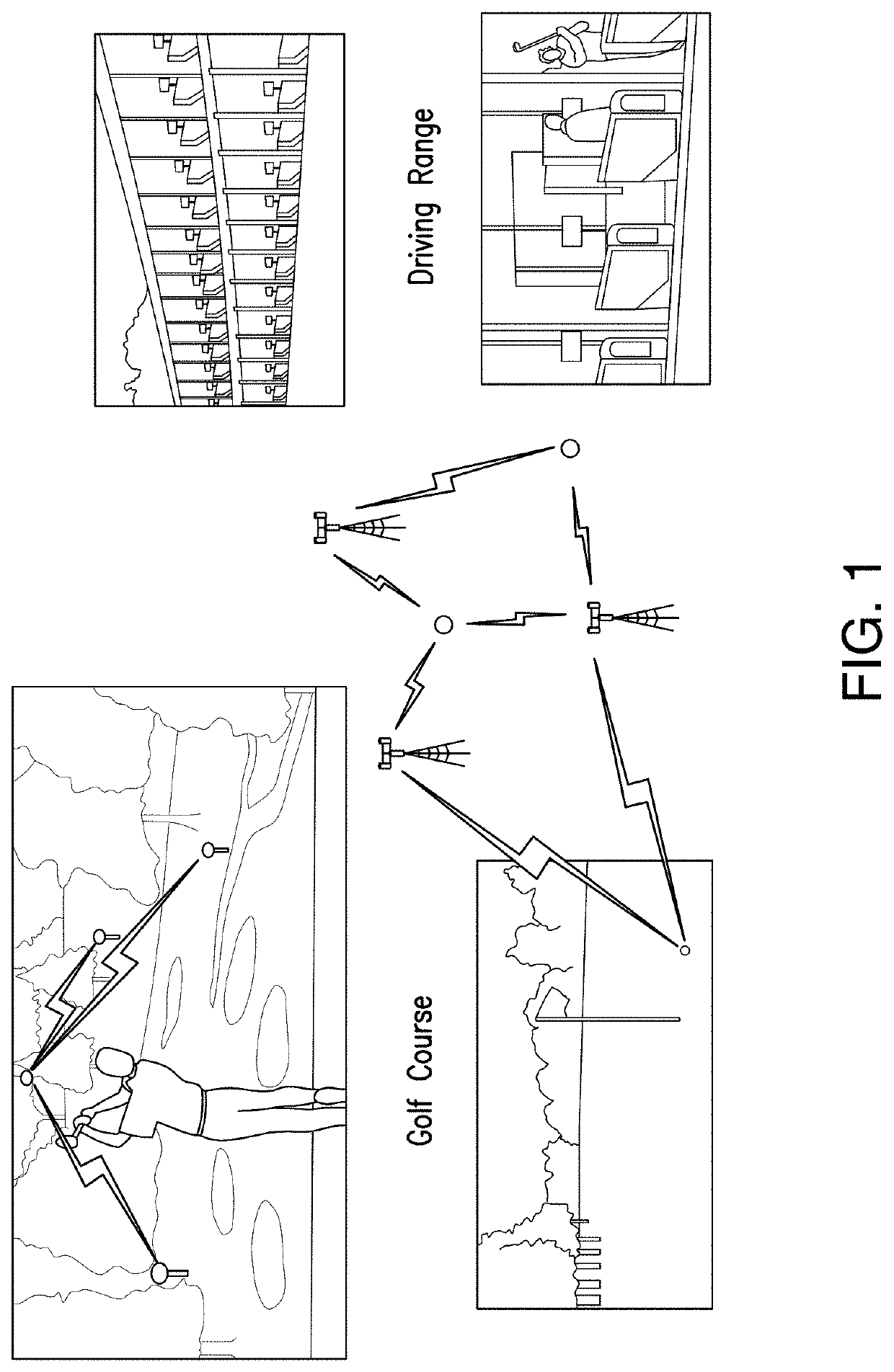
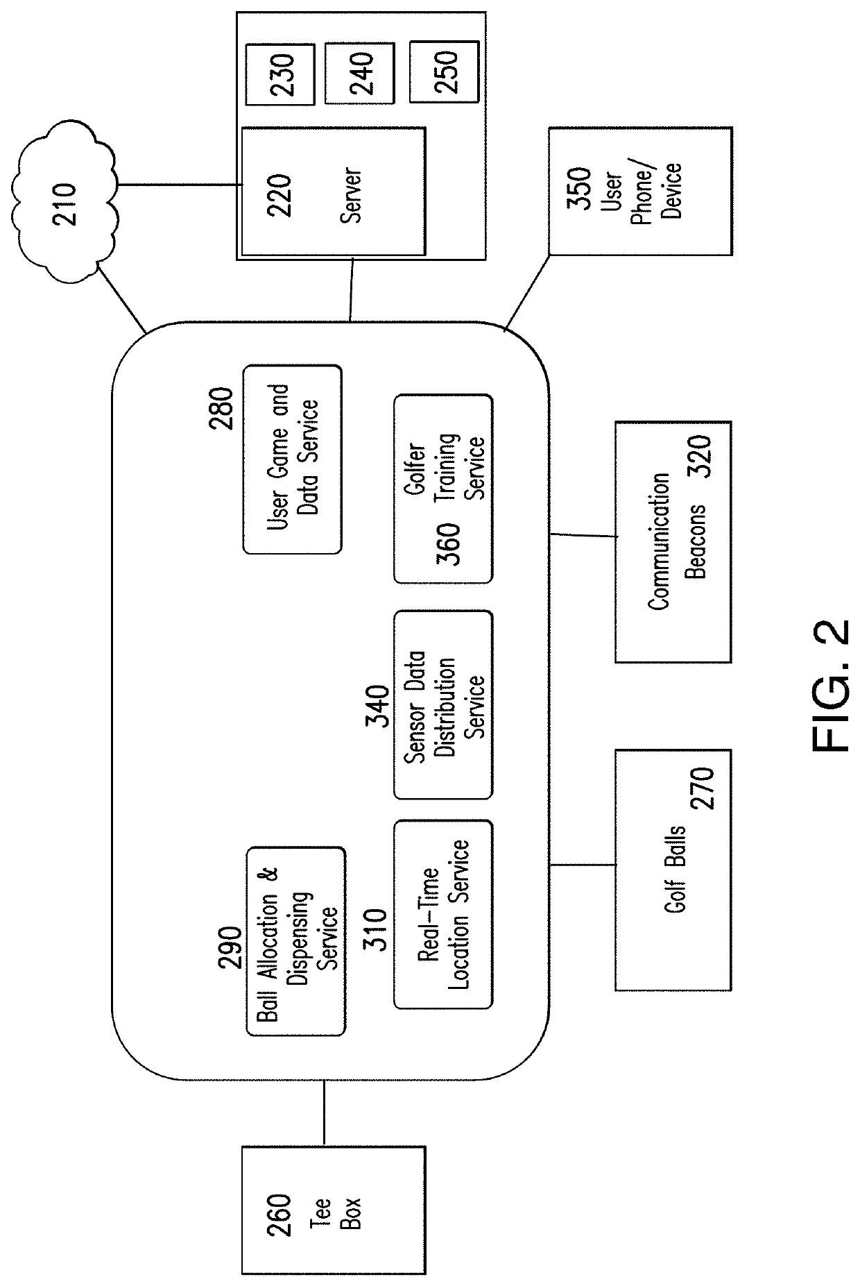
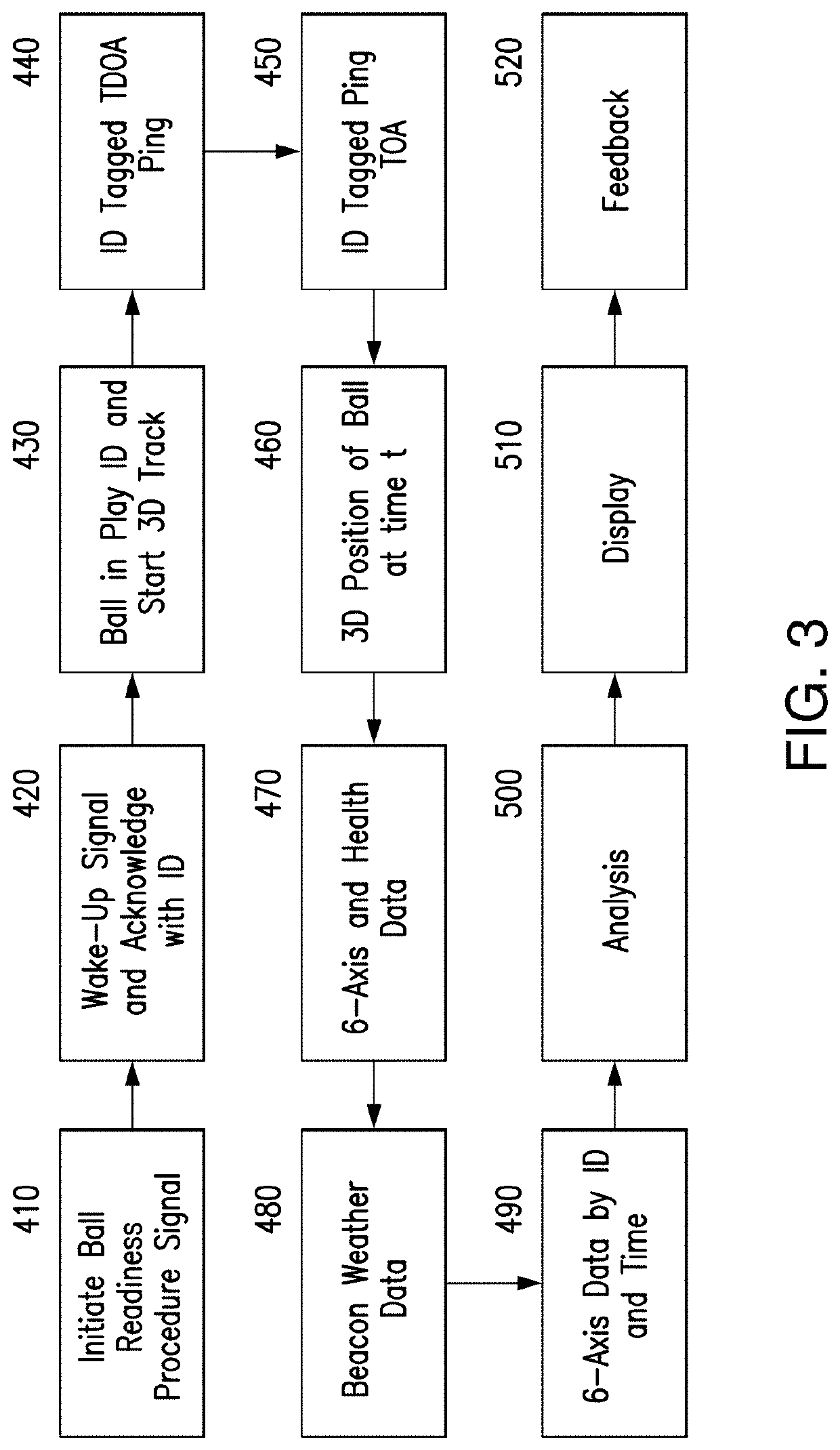
[0032]Embodiments of the invention provide for a golf ball tracking system that is capable of tracking multiple balls simultaneously using Radio Frequency (RF) technology of an Ultra-Wide Band (UWB) transmitter / receiver embedded in the center of a smart golf ball that would ping, in all directions, to external receivers that could then use Time Difference of Arrival (TDOA) techniques to locate the 3D position of the smart golf ball throughout its flight.

[0033]In further illustration, FIG. 1 pictorially shows a process for golf ball tracking. As can be seen, smart golf balls are equipped with RF transmitters, such as UWB transmitters. Beacons are set up throughout the golf course or driving range as RF receivers. After the smart golf ball is hit, TDOA techniques are then utilized to locate the 3D position of the smart golf ball throughout its flight. Both ends of the UWB TDOA system (ball electronics and beacon electronics) may operate in both receive and transmit modes. The 3D posit...


PUM


Abstract

Provided is a smart golf ball comprising: an inner electronics core, the inner electronics core comprising: a microcontroller with memory and at least one processor; a power supply in communication with the microcontroller; and an RF transmitter / receiver in communication with the microcontroller; an outer core surrounding the inner electronics core; and a skin layer covering the outer core. Also provided is a data processing system configured for golf ball tracking, comprising: a host computing system; a display in communication with the host computing system; one or more smart golf balls, each comprising a Real Time Location System (RTLS) Ultra-wideband (UWB) transmitter / receiver and a corresponding ID, in communication with the host computing system; three or more beacons, each comprising an RF transmitter / receiver, in communication with the host computing system; and a golf ball tracking module.

Description

CROSS-REFERENCE TO RELATED APPLICATIONS[0001]This application claims the benefit of U.S. Provisional Application No. 62 / 835,058 filed Apr. 17, 2019, the entirety of which is incorporated herein by reference.BACKGROUND OF THE INVENTIONField of the Invention[0002]The present invention relates to golf ball tracking systems and more particularly to golf ball tracking systems with radio frequency (RF) technology.Description of the Related Art[0003]Golf ball tracking systems allow golfers to track their shots in order to improve their performance. However, current golf ball tracking systems are lacking in many aspects in that the tracking systems do not actually track the golf ball accurately through space from impact to final resting position, nor do they provide real-time spin and position information, or are too costly for widespread commercial use. Furthermore, many of the golf ball tracking systems cannot be used for both driving range and on-course applications.[0004]Currently, metr...

Claims


Application Information

Patent Timeline
Patent Type & Authority Applications(United States)
IPC IPC(8): A63B43/00A63B37/00A63B24/00
CPCA63B2024/0034A63B2225/54A63B2220/40A63B24/0021A63B2220/833A63B43/004A63B37/0051A63B37/0024A63B37/0039A63B37/0075A63B37/0096A63B71/0622A63B2220/10A63B2220/30A63B2220/76A63B2220/803A63B2225/15A63B2225/50
Inventor CAREW-JONES, SAMUEL
Owner PFC SHARED SERVICES LLC
Learn More