
Automated collection and analysis of body fluids

a collection and analysis technology, applied in the field of body fluid collection, can solve the problems of high rate of skin breakdown and decubitis ulcer formation, inaccurate application of sealing layers, and high rate of diapers, etc., and achieves the effects of easy operation, high suction level, and low cos

Active Publication Date: 2020-11-05
UR24TECHNOLOGY INC
View PDF0 Cites 3 Cited by
  • Summary
  • Abstract
  • Description
  • Claims
  • Application Information

AI Technical Summary

Benefits of technology

The apparatus described in this patent allows for the temporary joining of a urine tube with a person's uretera, providing a means for urination without interrupting sleep or activities. The apparatus includes a low-level suction to maintain connection to the uretera, and a sensor to detect the presence of urine. The collected urine can be analyzed using known sensors and analytic techniques to monitor a person's biological signs. The apparatus is portable, low cost, and easy to operate, making it useful by paramedics in the field.

Problems solved by technology

Diapers are associated with a high rate of skin breakdown and decubitis ulcer formation while indwelling urinary catheters are a leading cause of urinary tract infections.
To enhance the seal, additional sealing layers have been proposed; however, such sealing layers are frequently applied incorrectly when the application requires that the individual applying the device independently establishes an optimal accurate application of the additional sealing layer(s).
Application of the additional sealing layer(s) is commonly inaccurate, with the additional sealing layer(s) being applied too proximal or too distal to other sealing layer(s) or with inadequate alignment to achieve an optimal bilaminar seal.
Molecules adsorbed on a microcantilever cause vibrational frequency changes and deflection.
Conventional biosensors need extensive packaging, complex electronic interfacing and regular maintenance.
The chip can last outdoors for at least a few years, although freezing temperatures may cause failure.

Method used


Image

  • Automated collection and analysis of body fluids
  • Automated collection and analysis of body fluids
  • Automated collection and analysis of body fluids

Examples


Embodiment Construction

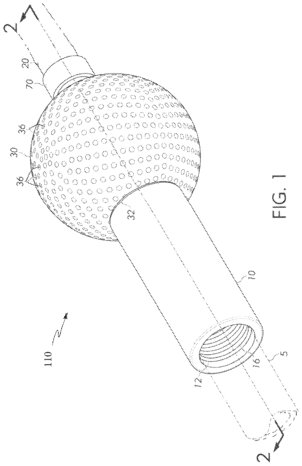
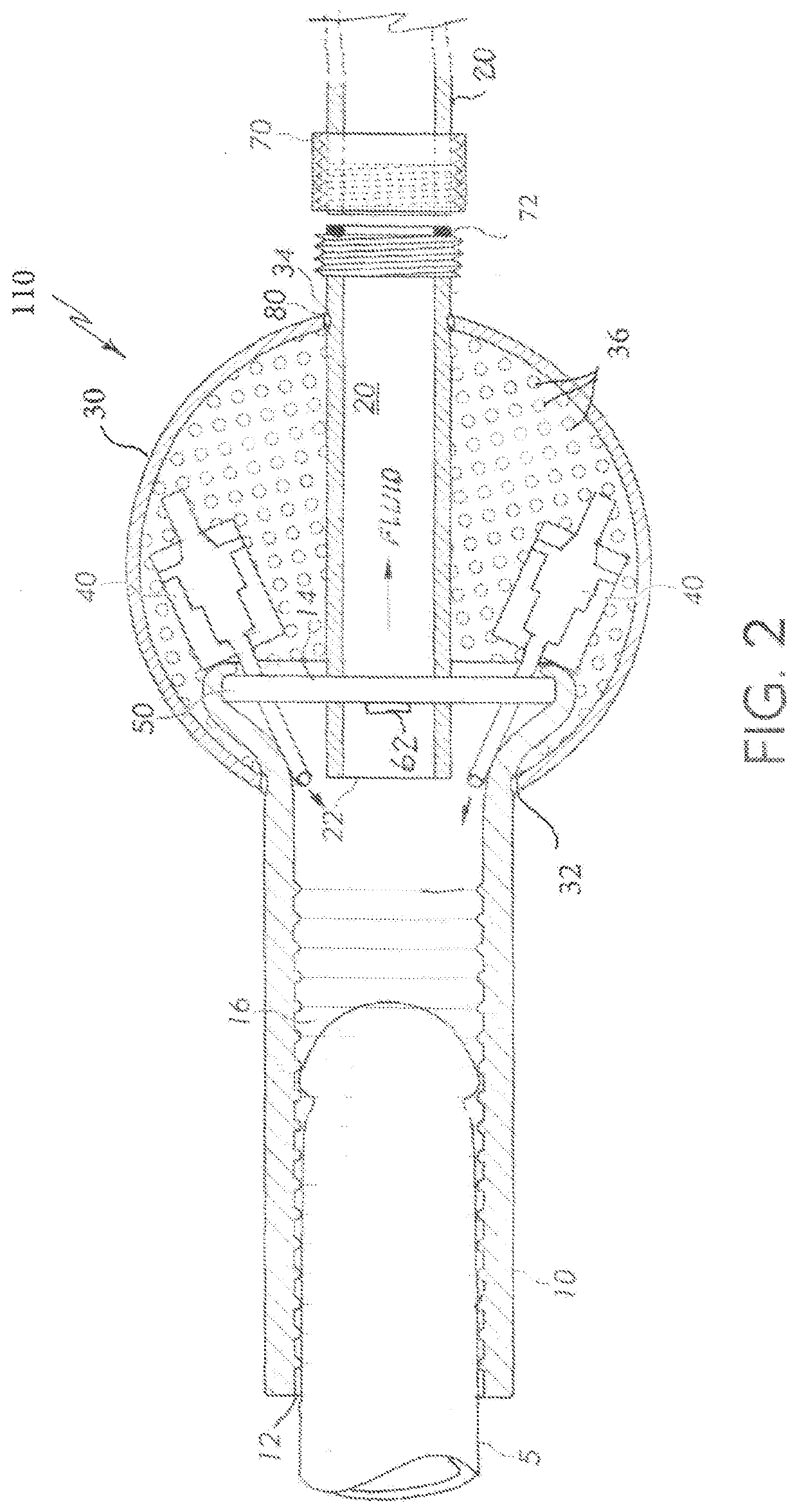
[0025]As shown in the attached drawing figures, a collector-analyzer apparatus includes an interface portion 110 (FIGS. 1 and 2) and a receiver portion 120 (FIGS. 5 and 6). These two portions are joined by a flexible interconnection tube 20 so that they may be conveniently set some distance apart during operation.

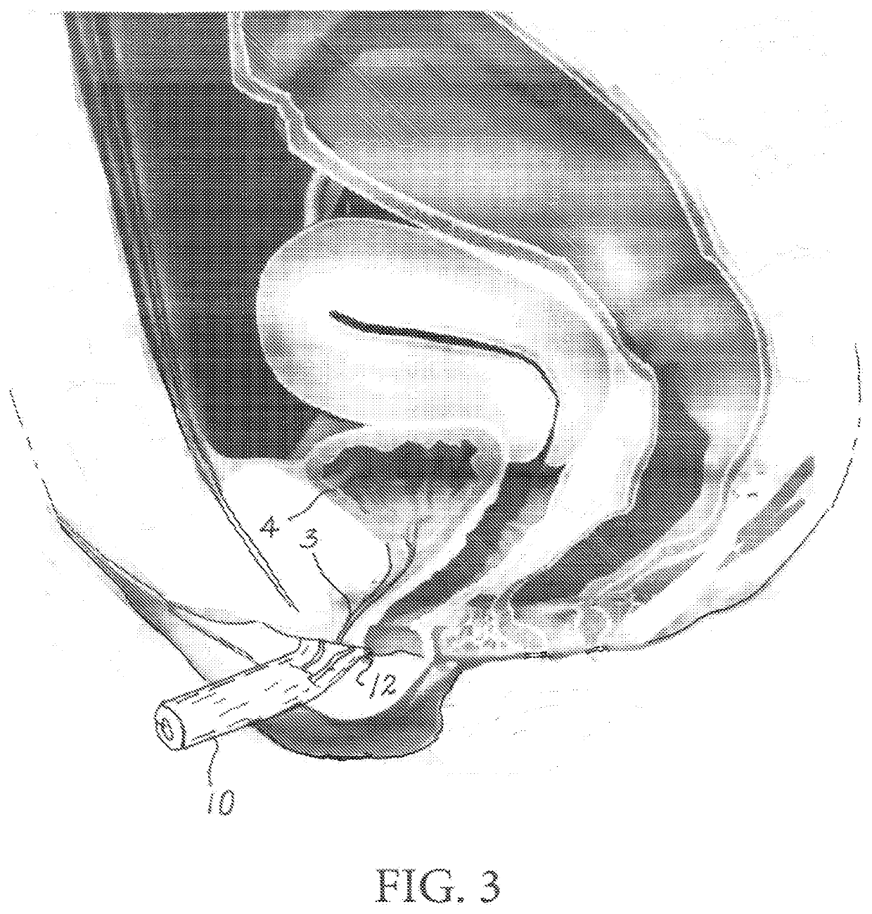
[0026]As shown in FIGS. 1 and 2 interface portion 110 is adapted for joining with the urethra, either male or female, and as such, enables reception of discharged urine; see the arrow labeled “fluid” in FIG. 2. These figures illustrate penis 5 which is inserted into proximal open end 12 of urine tube 10. Tube 10 may be of a transparent soft elastomeric material such as a silicone gel. Internal ribs 16 within tube 10 are shown and it is pointed out that they provide an improved gripping of tube 10 around penis 5 so that penis 5 is secured within tube 10 by suction action with no leakage. Shown also, are a spherical enclosure 30, vent holes 36 to allow air to enter enclosure ...


PUM

PropertyMeasurementUnit
threshold voltageaaaaaaaaaa
suctionaaaaaaaaaa
vibrational frequencyaaaaaaaaaa

Abstract

A method for collecting and analyzing urine at the time it is released uses a urine collecting tube joined with a canister. Suction is produced in the collecting tube to join the tube with a penis or to the exterior surface of a female urethra orifice. Once suction is achieved the collecting tube stays in place by suction action. When urine flows into the urine collecting tube a sensor triggers a vacuum pump to produce a higher level of suction to flush the urine into the canister where a level sensor determines the quantity of urine received. Various sensors in the canister determine levels of non-urine partials such as occult blood, drugs, salt and other substances. When urine is no longer detected within the urine tube, the vacuum pump is turned off and a low-level vacuum remains to assure interconnection with the urine tube.

Description

CROSS-REFERENCE TO RELATED PATENT APPLICATIONS[0001]Any and all applications for which a foreign or domestic priority claim is identified in the Application Data Sheet as filed with the present application are hereby incorporated by reference under 37 CFR 1.57.[0002]This application is a continuation of U.S. application Ser. No. 15 / 416,272, filed Jan. 26, 2017, which is a continuation-in-part of U.S. application Ser. No. 15 / 412,049, filed Jan. 22, 2017. U.S. application Ser. No. 15 / 416,272 claims the benefit of U.S. Provisional No. 62 / 297,096, filed Feb. 18, 2016. Each of the above-listed disclosure are incorporated herein by reference in their entirety.BACKGROUND OF THE INVENTIONField of the Invention[0003]The present invention relates to the collection of body fluids, particularly urine, and to a method of automated collection and analysis.Brief Discussion of the Related Art[0004]Male urinary collection and analysis is common for medical reasons. This is managed in the prior art w...

Claims


Application Information

Patent Timeline
Patent Type & Authority Applications(United States)
IPC IPC(8): A61B10/00A61B5/20G01N33/487G01N33/493
CPCA61B10/007G01N33/48778G01N33/493A61B5/207A61B2505/07A61B2505/03A61B5/208A61B5/6852A61B5/6808
Inventor DUVAL, LANDON
Owner UR24TECHNOLOGY INC
Learn More